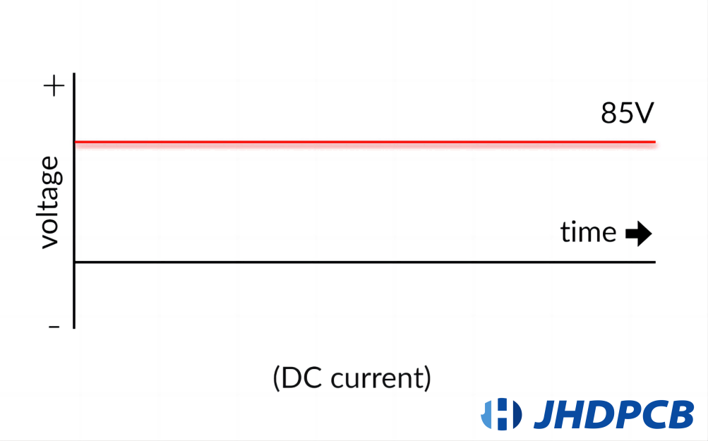

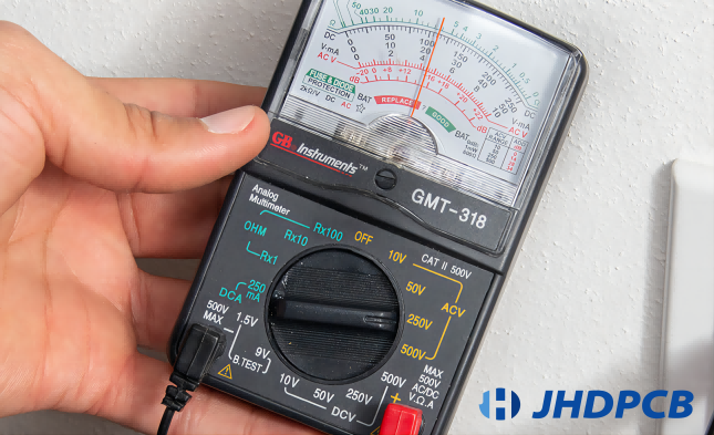
The Unicode character U+2393, often denoted as “⎓,” holds significance in the realm of DC applications.Graphically, it is represented as a linear path.The symbol for DC voltage on a multimeter is a capital letter “V” with a straight line above it (― V). This symbol indicates the measurement range for direct current voltage.
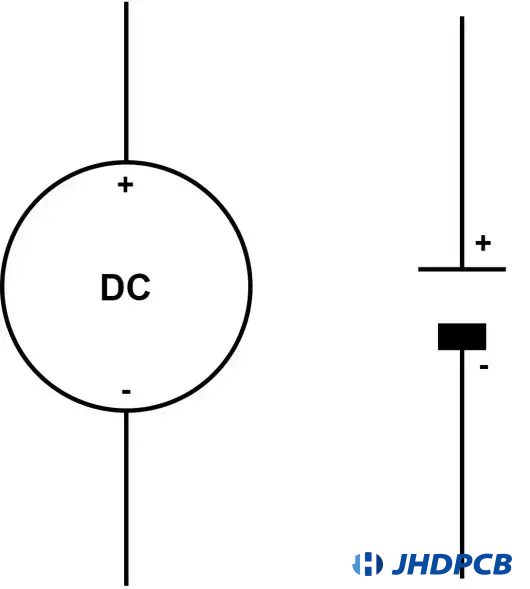
In circuit diagrams and schematics, the symbol used to represent a DC voltage source, such as a battery, consists of two parallel lines—a solid line and a dashed line. The solid line symbolizes the positive terminal (+), while the dashed line represents the negative terminal (-). This particular symbol is extensively utilized to indicate the presence of a DC voltage source.
The positive terminal (+) of the DC voltage source is represented by the longer line, whereas the negative terminal (-) is denoted by the shorter line. Typically, the positive terminal is associated with a higher potential or voltage, while the negative terminal corresponds to a lower potential or voltage.
It should be noted that the exact symbol may exhibit slight variations depending on the specific standards or conventions followed. Nevertheless, the fundamental depiction of a straight line accompanied by a shorter line parallel to it is broadly recognized as the symbol for a DC voltage source.
Utilize a multimeter for the assessment of direct current (DC) voltage. The underlying principle remains consistent regardless of the DC voltage measurement location. Perform a comparable procedure to check the voltage of a power bank, similar to that employed for a battery.
Please follow these instructions to examine the charge level of a battery:
- Detach the battery from any power tools or chargers. In the case of car batteries, they can be tested in situ after leaving the headlights on for two minutes and subsequently turning them off.
- Insert the black probe into the shared socket.
- Connect the red plug into the jack labeled for DC voltage, VΩ, or V–.
- Position the black connector on the minus (-) terminal of the battery.
- Place the red probe onto the positive terminal.
- Make a record of the measurement indicated on the multimeter.
- First, detach the red probe, followed by disconnecting the black probe.
Pro-tip: In the event that your digital multimeter exhibits a negative reading, interchange the black and red probes to obtain a positive reading. The numerical value should remain the same, but without a negative symbol preceding it. Exercise caution when handling an analog multimeter to avoid interchanging the positive and negative terminals, as this could potentially lead to damage to the device.
| Basis for Comparison | AC Voltage | DC Voltage |
|---|---|---|
| Definition | The AC voltage serves as the driving factor behind the oscillating flow of current between two points. | The DC voltage generates the unidirectional flow of current between two points. |
| Iconic Depiction | 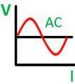 | 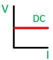 |
| Frequency | Varies by nation. | Zero |
| Coefficient of Efficiency | Ranges from 0 to 1. | 0 |
| Direction | Alters | Remains Consistent |
| Orientation | Fluctuates | Stays unchanged |
| Derived from | Dynamo | Unit or Accumulator |
| Effectiveness | Elevated | Poor |
| Inert Attribute | Reactance | Conductance |
| Magnitude | Possess | Lack |
| Transformation | Through utilization of inverter. | Through utilization of rectifier. |
| Converter | Necessitates for transfer. | Not necessitates. |
| Line and Ground | Posess | Do not possess |
| Advantages | Easy to measure. | Easily amplify |
| Electron motion | The electrons oscillate and change their direction periodically in an alternating manner. | The electrons undeniably move in a consistent direction without any change. |
| Category | Sine, Square, Trapezoid, and Triangle signal. | DC is often categorized as pulsating and pure DC. |
| The load type | Conversely, AC voltage interfaces with different categories of loads, namely capacitive, inductive, and resistive loads. | It exclusively interfaces with the resistive load category. |
| Hazardous | When managed irresponsibly, it is unquestionably perilous. | DC electrical power poses a greater danger in comparison to AC power with a similar rating. |
| Application | Conversely, AC is utilized by domestic and industrial devices such as dishwashers, refrigerators, and toasters. | Mobile phones, LCD televisions, portable lights, electric and hybrid cars, and so on. |
| Source | Conversely, it operates on an alternating current (AC) circuit and generator. | It utilizes both a direct current (DC) battery and a power generator. |
| Electric power transportation | It can also be transported through high-voltage direct current (HVDC) systems. | In terms of power or electrical supply, the most advanced transmission method is through high-voltage direct current (HVDC) systems. Furthermore, in this system, direct current (DC) exhibits minimal voltage loss. |
| Types of Sweeps | The AC frequency analysis is specifically formulated to compute the small-signal voltage reaction of a circuit. | The current source mode typically calculates the operating point of specified power sources in predefined increments across a range of voltage values. Moreover, the DC sweep functionality is compatible with any source that has a variable DC component. |
| Scan type | The usual operation of this scanning method involves conducting a sample cycle at the designated speed to determine timing conformance. | The scanning rate ranges from 100 milliseconds to 10,000 seconds. Furthermore, it is capable of operating with either a ramp or triangle waveform. |
Having a clear comprehension of the disparity between alternating current (AC) and direct current (DC) voltage is essential for identifying suitable applications and designing electrical systems accordingly.
Rectification refers to the transformation of an alternating current (AC) power source into a direct current (DC) power source. Rectifiers are devices designed to convert AC supply into DC supply. Fundamentally, this conversion process can be subdivided into four sequential stages:
1.Voltage reduction
Typically, an alternating current (AC) power source operates at a high voltage level due to its efficient transmission with minimal losses. Nonetheless, our devices require a lower voltage supply. To achieve this, a step-down transformer is employed. In step-down transformers, the primary coil consists of a greater number of turns compared to the secondary coil.
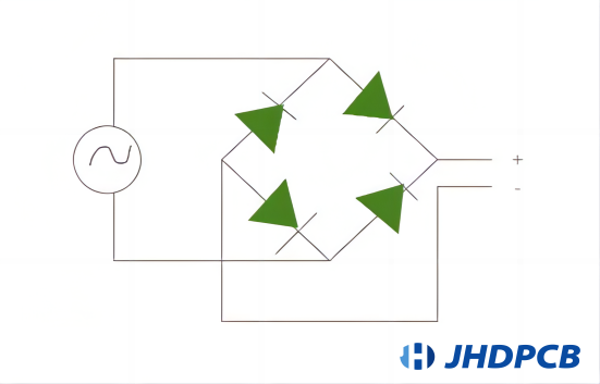
2.AC to DC conversion
Following the voltage reduction process, alternating current (AC) is transformed into direct current (DC) through the use of rectifiers to convert DC voltage. A full bridge rectifier can be employed for this purpose. This device utilizes four diodes that operate in a forward bias and not in a reverse bias. In the positive phase, two diodes are operational, whereas in the negative phase, the other two diodes are activated. In this manner, the AC supply is rectified into a DC supply to convert DC voltage. The image below depicts a full-bridge rectifier circuit utilized for converting AC to DC.
3.Refining DC waveforms
The DC waveforms produced during the previous stage may exhibit pulsating characteristics and fluctuations, lacking pure DC waveforms. Capacitors are utilized to address this issue. Capacitors act as devices to store energy when the input voltage rises from zero to its peak value. The energy stored in the capacitor can be discharged when the input voltage decreases back to zero. This process effectively smoothens the waveforms to a considerable extent.
4.Stabilizing DC voltage
Ultimately, the DC voltage is adjusted to a predetermined and constant value by employing a voltage regulator integrated circuit (IC). The voltage regulator IC is comprised of an integrated electronic circuit that performs the final conversion of our DC supply to the desired voltage level. For instance, the 7805 Voltage Regulator IC is utilized to convert the DC supply to a fixed 5V output, while the 7809 Voltage Regulator IC is used to convert the DC supply to a fixed 9V output.