A simple start-stop circuit is a basic electrical circuit that controls the operation of a motor or any other electrical device. It comprises of a commencement button, a cessation button, and a relay or contactor.
Once the initiation button is pressed, it activates the control circuit and completes the essential connections to enable the transmission of electrical energy to the motor. This causes the motor to start running. The start button is usually configured as a momentary push-button, meaning it only remains closed as long as it is being pressed.
On the other hand, when the stop button is pressed, it interrupts the control circuit and opens the contacts that allow power to flow to the motor. This stops the motor from running. Like the start button, the stop button is also typically a momentary push-button.
The start-stop circuit is designed to provide a simple and safe means of controlling the operation of a motor. It allows an operator to easily start and stop the motor as needed, providing control and safety in various applications such as industrial machinery, conveyor systems, and pumps.
Buttons/Contacts
Press buttons and contacts are vital constituents within a start-stop circuit that facilitate the connection and disconnection of power in an electrical circuit. These devices play a crucial role in controlling the circuit’s operation by providing a means to initiate or terminate its function.
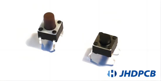
Push buttons are mechanical switches that are commonly utilized to initiate or terminate the circuit. They are designed to be momentary, meaning they only maintain contact for as long as they are being pressed. When the push button is pressed, it completes the circuit, allowing electricity to flow and powering the associated equipment or machinery.
Contacts, on the other hand, are electrical components that make or break an electrical connection within the circuit. There are two primary types of contacts used in electrical circuits: Normally Open (NO) and Normally Closed (NC). A Normally Open contact remains open until it is closed by pressing the push button, thereby allowing current to flow. On the contrary, a Normally Closed contact starts in a closed state, but when the push button is pressed, it opens, resulting in the interruption of the circuit and cessation of the current flow.
In a contactor start stop circuit, the push button connected to the coil of a magnetic contactor or relay controls the flow of power. Once the start button is pressed, the normally open contact linked to it will shut, energizing the coil and initiating the operation of the contactor or relay. This, in turn, allows power to flow to the load or equipment connected to the circuit. When the stop button is pressed, the normally closed contact associated with it opens, de-energizing the coil and cutting off power to the load, effectively stopping its operation.
By utilizing push buttons and contacts in a start-stop circuit, operators can safely and conveniently control the energizing and de-energizing of electrical equipment, ensuring proper functioning and preventing potential hazards.
Relay/Contactor
Relays and contactors are electromagnetic devices employed in start-stop circuits to regulate the functioning of other electrical elements linked to them. They act as switches that can handle higher currents or voltages than what the control circuit can handle directly.
In a start-stop circuit featuring a relay, the coil of a contactor is generally interconnected with the start-stop control circuit operating at a lower voltage. Upon pressing the start button, the coil receives power, resulting in the generation of a magnetic field. This magnetic field pulls in the contacts within the contactor, closing the main power contacts. The closed contacts then allow the supply voltage to flow to a motor or other electrical loads connected to the circuit.
The primary advantage of using a contactor in this setup is its ability to handle high currents or voltages safely. By employing a lower voltage control circuit to energize the contactor coil, operators can control the flow of power to larger electrical loads without the need for additional wiring or specialized control devices.
Relays function similarly to contactors but are typically used for lower-power applications. They are often found in control panels or smaller circuits where the current or voltage requirements are within their rating. Relays also have a coil that, when energized, creates a magnetic field that attracts the relay contacts, closing or opening the circuit as needed.
Both relays and contactors are crucial for controlling various electrical components in a start-stop circuit, such as motors, solenoids, lights, or heaters. Their ability to switch high currents and voltages ensures the safe and efficient operation of these devices based on the inputs received from the start and stop buttons or switches.
Motor
Motors are electromechanical mechanisms that convert electrical energy into kinetic energy, enabling the locomotion and operation of various systems and equipment. They are commonly utilized in start-stop control circuits, particularly in applications like conveyor belts and process machinery where controlled movement is necessary.
In a electrical start stop circuit, motors are connected to the output side of relays or contactors, which are controlled by start and stop buttons. When the initiation button is activated, the relay or contactor gets energized, delivering power to the motor. Electrical energy is then transformed within the motor into kinetic energy, which drives the mechanical load.
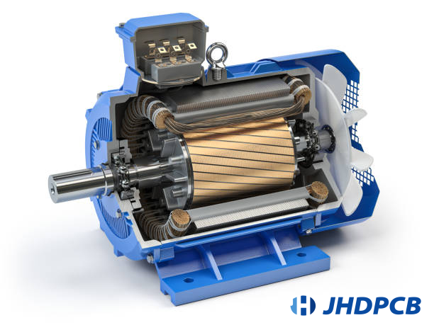
The transformation of electrical energy into kinetic energy occurs through the interaction of magnetic fields within the motor. The motor consists of coils or windings that produce a magnetic field when an electric current passes through them. This magnetic field interacts with the magnetic field generated by permanent magnets or other windings, resulting in a rotational force known as torque. This torque causes the motor’s rotor to rotate, generating mechanical motion.
Various kinds of motors are utilized based on the specific demands of the given application. Induction motors, for example, are commonly employed in industrial systems due to their robustness and reliability. Synchronous motors are often used in situations where precise speed control is essential, while brushed or brushless DC motors offer advantages such as high efficiency and compact size.
Overall, motors are integral components in start-stop control circuits, allowing for the conversion of electrical energy into mechanical energy. Their ability to generate kinetic energy is instrumental in driving conveyor belts, operating process machinery, and facilitating movement in a wide range of industrial and commercial settings.
Overload
Overload pertains to a condition in which the electrical current passing through a circuit surpasses its intended capacity. This can occur due to a surge in voltage or an excessive load being connected to the circuit. When an overload happens, it poses a risk to the components and wiring within the circuit.
To mitigate this risk, overloads are typically protected by various devices. A frequently utilized tool is a fuse, which is specifically engineered to undergo melting and disrupt the circuit in the event of an overcurrent. This cessation of electric current flow acts as a safeguard against potential harm to the components and wiring.
An alternative protective mechanism is a circuit breaker. Circuit breakers operate in a comparable fashion to fuses but offer the advantage of being resettable after being triggered. They automatically detect overcurrent conditions and open the circuit to protect against damage. Once the issue has been resolved, the circuit breaker can be restored, either manually or automatically, allowing for the continuation of electric current flow.
Both fuses and circuit breakers are essential for electrical safety as they prevent overheating and potential fires that could result from an overload. By disrupting the circuit, these protective devices restrict the magnitude of current passing through the system, guaranteeing that it stays within secure operational thresholds.
In addition to fuses and circuit breakers, other forms of protection devices exist, such as surge protectors and thermal overload relays. Surge protectors safeguard against voltage spikes, which can occur during lightning strikes or sudden power surges. Thermal overload relays, on the other hand, monitor the temperature of components and disconnect the circuit if it exceeds safe levels.
In general, the utilization of overloads or protective devices is essential for preserving the reliability and safety of electrical circuits. They play a critical role in averting harm to components, reducing the potential for electrical risks, and guaranteeing the dependable functionality of electrical systems.
A control apparatus equipped with contacts, known as a two-wire control, possesses the capability to either initiate or terminate the functioning of the pilot device. In order to prevent circuit damage, smaller loads that rely on fewer connections need to operate at low current levels. Hence, two-wire controllers can be employed for managing motors or lights. In this setup, releasing the button disengages the coil, resulting in closed contact and ensuring proper operation.
To implement a 2-wire control in a start-stop circuit, a starter coil is connected in series with a contact-based pilot device. The pressure or limit switch is the predominant type of contact pilot device used in most applications.
In situations where the circuit needs to operate independently, the 2-wire control is utilized. In this setup, if a power outage occurs while the switches’ contacts are closed, the relays will automatically activate. As a result, when the power is restored, the circuit is completed. In the 2-wire control arrangement, the starter and pilot device are linked solely by a pair of wires.
Operating Process –
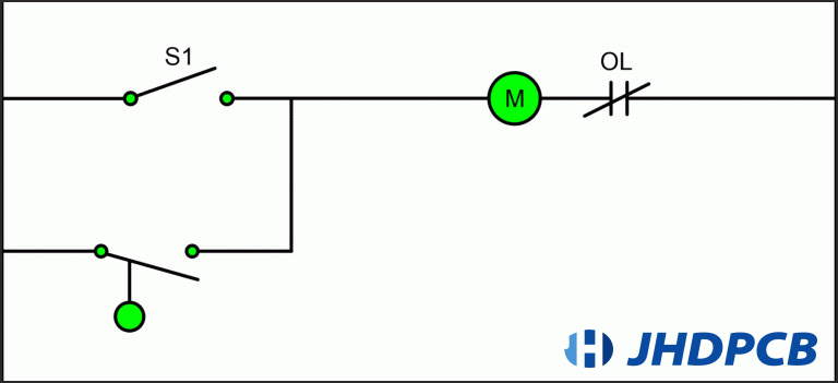
- If the toggle closes the single pole switch for the entire duration, the motor starter will be activated and remain activated.
- If the designated single pole switch, S1, is left open, the liquid level switch in the circuit will take control of whether the motor starter is turned on or off.
- As either the single pole switch or the liquid level switch can energize the motor starter coil in the control circuit at any given moment, the load connected in this circuit will remain activated unless there is a loss of power to the entire control circuit.
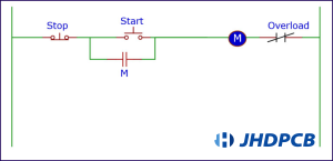
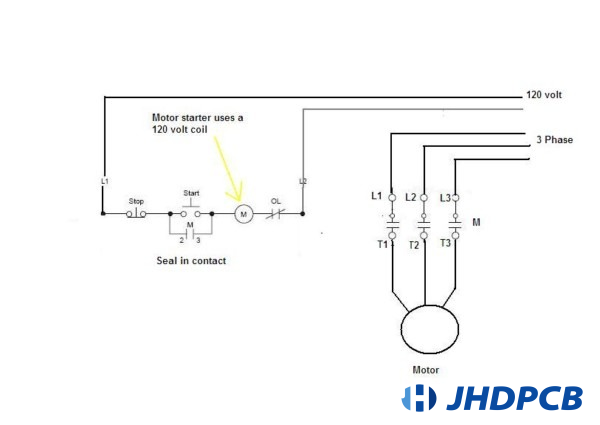
The start/stop control position circuit exemplifies a three-wire control circuit. It primarily relies on normally open and normally closed contact points, start/stop stations, and a seal-in contact that opens upon activation. By establishing parallel connections between this contact and the start button, it allows for the control of the voltage applied to the coil. This setup operates differently compared to a two-way control circuit as it involves fewer components.
To establish a connection in a 3-wire start-stop circuit between the starter and the pilot device, it requires the presence of three wires. The purpose of these wires is to provide power to the starter coils. The 3 wire start stop circuit typically utilizes momentary switches to “start” or “activate” the starter, meaning the switches need to be held down for the starter to remain active. This ensures that the motor continues to run as long as the start button is pressed and releases once the stop button is pressed, breaking the circuit and stopping the motor.
To initiate the closing of the circuit, an external stimulation is required, such as briefly pressing a start button. Additionally, you can parallel a secondary starter circuit with the start button. This ensures that once the start button is released, the motor continues to receive power and remains powered up.
Operating Process –
- When the start pushbutton is activated, electricity is supplied to the coil.
- When the coil receives power, the armature of the pilot device and the memory/seal-in contact make contact.
- When the coil is powered, both the armature of the pilot device and the memory/seal-in contact come together.
- The equipment linked to the motor initiator (M) obtains complete input voltage and persists in operating until the cessation press switch or the motor experiences an overload.
- When the stop pushbutton is pressed, it interrupts the control voltage flow through the memory/seal-in contact, leading to the de-energization of the coil. This allows the line voltage to reach the connected loads, resulting in their shutdown.(In case of a power failure, the circuit returns to the de-energized state. Therefore, the start button needs to be briefly pressed again to initiate the closing of the circuit.)
Start-stop Jog Circuit
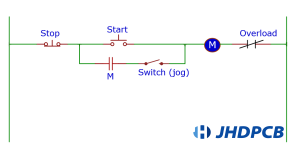
The start-stop jog circuit is an electrical control circuit commonly used in industrial applications. It allows for the control of electric motors or other machinery by providing a means to start, stop, and jog their operation.
Within this circuit, three primary elements can be identified: the start button, the stop button, and the jog button. The start button is employed to commence the motor’s operation, whereas the stop button is utilized to bring it to a halt. The jog button, on the other hand, is used for temporary or momentary operation of the motor.
When the start button is pressed, it closes a normally open contactor, allowing current to flow through the motor, which starts running. At the same time, the stop button is opened, breaking the circuit and preventing accidental starting or restarting of the motor.
To halt the motor, the stop button is pressed, causing the contactor to open and interrupting the power flow to the motor. This ensures the motor stops quickly and safely.
The jog button is employed when there is a need for an intermittent or precise movement of the motor in a latching start-stop circuit. When the jog button is pressed and held, it bypasses the start button and provides power to the motor without latching the contactor. This feature allows for manual adjustment or positioning of machinery without engaging the full start sequence typically associated with a latching start-stop circuit. So, the jog button provides temporary power to the motor, enabling precise control over its movement while still maintaining the functionality of the latching start-stop circuit for regular operations.
Overall, the start-stop jog circuit provides a convenient and safe way to control the operation of motors and machinery in industrial settings. Its modular design allows for easy integration into various control systems, making it widely used in manufacturing, automation, and other industrial applications.
Start-stop Circuits With A Motor Connected
Start-stop circuits are electrical circuits that control the operation of a motor. They are widely utilized in industrial and commercial settings to initiate and terminate motor operations conveniently and effectively.
In a start-stop circuit, a motor is connected to a power supply through a control device, such as a push button or a switch. Upon pressing the start button, the circuit becomes complete, enabling the current to pass through and reach the motor. This initiates the motor’s rotation and starts its operation.
Once the motor is in operation, it can be brought to a stop by either pressing the stop button or breaking the circuit. This action disrupts the current flow to the motor, leading to its cessation.
Start-stop circuits are designed to ensure the safe and controlled operation of motors. They provide a convenient way to start and stop motors without the need for manual intervention, reducing the risk of accidents and improving productivity.
Moreover, start-stop circuits frequently incorporate safety measures like overload safeguards and emergency stop buttons to guarantee the motor’s operation is secure and dependable.
Overall, start-stop circuits with a motor connected are essential components in various industries, enabling efficient and controlled motor operation.
After the button is pressed, an electric current flows through the circuit, resulting in the activation of the motor.
As can be seen, the motor commences its functioning when an electrical current passes through the coil of a contactor.
Releasing the start button or pressing the stop button disrupts the current flow. Once the start button is released, the current will no longer circulate throughout the circuit. The same outcome is observed when the stop button is pressed. Consequently, without power applied, the motor will not operate.
plc start stop circuit
A PLC start-stop circuit and a traditional start-stop circuit have a common purpose, which is to regulate the functioning of a motor or other electrical apparatus. Both circuits consist of a start button and a stop button, which are used to initiate and interrupt the operation of the motor.
However, the main difference between the two circuits lies in the control mechanism. In a traditional start-stop circuit, the start and stop buttons are directly connected to control relays or contactors, which physically open and close the electrical connections to the motor. This type of circuit relies on mechanical components for control.
On the other hand, a PLC motor start stop circuit utilizes a Programmable Logic Controller (PLC) as the control mechanism. The start and stop buttons are connected to the inputs of the PLC, which processes the signals and controls the output relays or contactors. The PLC can be programmed with complex control logic and can perform additional checks and operations before starting or stopping the motor.
The use of a PLC in the start-stop circuit provides several advantages over the traditional circuit. It offers greater flexibility and programmability, allowing for more complex control sequences and logic operations. The PLC can also incorporate safety features, such as emergency stop functionality and fault detection capabilities. Additionally, the PLC allows for easier integration with other automation systems and can provide diagnostic and monitoring capabilities.
In summary, while both a PLC start-stop circuit and a traditional start-stop circuit serve the same purpose of controlling the operation of a motor, the use of a PLC in the former provides enhanced control, flexibility, and safety features.
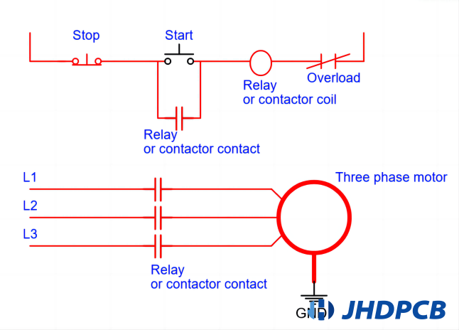
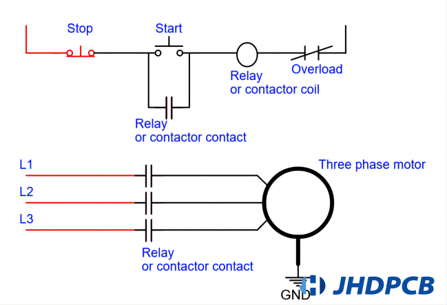
3-phase motor start-stop circuit
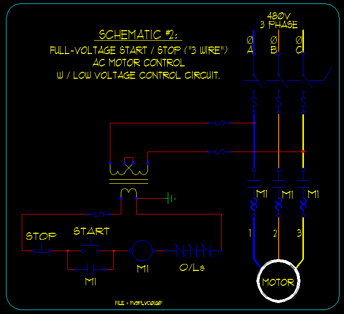
The 3-phase motor start-stop circuit is a specific type of start-stop circuit that is designed specifically for controlling 3-phase motors.
A start-stop circuit, in general, refers to an electrical control circuit that allows the user to initiate or halt the operation of equipment or machinery. It typically consists of switches, relays, and other control components. This type of circuit can be used for various applications and devices.
The 3-phase motor start-stop circuit, as the name suggests, is tailored for starting and stopping 3-phase motors, which are commonly used in industrial settings due to their high power output and efficiency. These motors require a specialized control circuit to handle the unique characteristics associated with their operation, such as multiple phases and the need for motor protection.
The 3-phase motor start-stop circuit includes key components such as contactors, thermal overload relays, and control switches. Contactors are electromagnetic switches specifically designed to handle the high current of the 3-phase motor. They provide a means to energize or de-energize each phase of the motor.
Thermal overload relays are used to protect the motor from excessive current or overheating. These devices monitor the motor’s current draw and trip if it exceeds a preset threshold, preventing damage to the motor.
Control switches, such as start and stop buttons, are used to initiate or halt motor operation. When the start button is pressed, the circuit is closed, allowing current to flow through the motor windings and start the motor. The start contactor is energized and latches itself into position to keep the motor running. The stop button, when pressed, opens the circuit, de-energizing the contactor and stopping the motor.
In summary, the 3-phase motor start-stop circuit is a specialized version of the start-stop circuit designed specifically for 3-phase motors. It incorporates components and safety features that cater to the unique requirements of these motors, ensuring reliable and safe operation in industrial applications.
remote start stop control circuit
A remote start-stop control circuit is a type of electrical circuit that allows for the remote operation of a motor or electrical device. It enables the user to start or stop the motor from a distance, without the need to physically press buttons near the motor.
The circuit typically consists of a transmitter and a receiver. The transmitter is a remote control device that sends signals wirelessly to the receiver, which is connected to the start-stop circuit of the motor.
When the user pushes the initiation button on the transmitter, it transmits a signal to the receiver. The receiver receives the signal and initiates the start operation of the motor, enabling it to commence running. Likewise, when the stop button on the transmitter is pressed, the receiver receives the signal and activates the stop function, resulting in the cessation of the motor.
The remote start-stop control circuit adds convenience and flexibility to motor control applications, especially when the motor is located in a hard-to-reach or hazardous area. It eliminates the need for direct physical interaction with the motor and provides the user with the ability to control the motor remotely.
What is the purpose of a Start-Stop circuit?
The primary purpose of a Start-Stop circuit is to provide a user-friendly and efficient method to control motor-driven devices. It allows users to initiate motor action when necessary and stop it quickly in emergency situations or during maintenance tasks.
Are there any safety precautions associated with the Start-Stop circuit?
Yes, safety is a crucial aspect of designing a Start-Stop circuit. Several safety measures can be incorporated, including overload protection, which prevents the motor from drawing excessive current, short-circuit protection to safeguard against electrical faults, and emergency stop features that enable an immediate shutdown in critical situations.
Where are Start-Stop circuits commonly used?
Start-Stop circuits find widespread applications in various motor-driven equipment across industries. They are commonly employed in pumps for water systems, conveyor systems in manufacturing facilities, compressors, fans, and industrial machinery. These circuits are extensively utilized in sectors such as production, farming, and mechanization.
Can multiple Start-Stop circuits be interconnected?
Absolutely! It is possible to interconnect multiple Start-Stop circuits to control multiple motors or complex systems. Interconnection can be achieved by utilizing auxiliary contacts and interlocking mechanisms between the circuits. This allows for synchronized control and coordination of multiple motors or processes.
How can overload protection be implemented in a Start-Stop circuit?
Overload protection can be implemented by using overload relays. These relays oversee the current that flows to the motor and activate the circuit breaker if the current surpasses a predetermined threshold, safeguarding the motor against potential harm.
Can a Start-Stop circuit be used with different types of motors?
Yes, a Start-Stop circuit can be used with various types of motors like induction motors, synchronous motors, and DC motors. The circuit design may need to be adapted based on the specific motor type and its control requirements.
Are there alternative control methods for motor operation besides Start-Stop circuits?
Yes, besides Start-Stop circuits, other control methods like variable frequency drives (VFDs) and soft starters can be used to control motor speed and starting/stopping operations. These methods provide smoother acceleration/deceleration and energy-saving benefits.
Can a Start-Stop circuit be automated?
Yes, a Start-Stop circuit can be automated by incorporating additional control elements like timers, sensors, and programmable logic controllers (PLCs). This allows for automatic motor control based on predefined parameters or external input signals.
What is the auto start and stop generator control circuit?
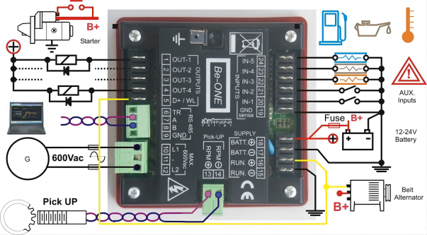
The auto start and stop generator control circuit is a system that automatically initiates or halts the operation of a generator based on predefined conditions. It utilizes sensors or devices to monitor factors such as power demand, voltage levels, or battery charge status. When specific conditions are met, the control circuit triggers the generator to start or stop its function. The auto start and stop generator control circuit is closely related to the Start-Stop circuit, as it essentially controls the starting and stopping process of the generator. However, the auto start and stop generator control circuit involves additional monitoring and sensing elements to ensure optimal generator operation and energy efficiency.