Why choose JHDPCB?
- Real PCB and PCBA manufacturers;
- Meet industry certification and production standards;
- 99.48% delivery on time;
- 10+ years of industry experience;
- 150+ experienced R&D team;
- 3000+ orders/day;
contact us
Provide quality service for your PCB project. Tel: +86 755 2753 9533
PCB design guide
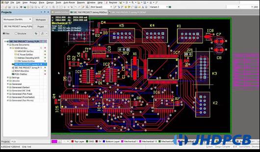
PCB design is one of the most important design elements in electronic product design. In most cases, an electronic hardware design engineer will design the circuit, and then a PCB layout expert will do the PCB layout and design based on schematics provided using a PCB CAD system. A good PCB design can greatly reduce the cost of the board and minimize the risk of errors in the PCB manufacturing process.

The main common standard for PCB design is IPC-2221B. It provides manufacturability and quality rules such as material property requirements, surface plating standards, conductor thicknesses, component placement, dimensional and tolerance rules, and more. This standard applies to all printed circuit board types, including single-sided PCB, double-sided PCB and multi-layer PCB or HDI PCB. For a specific technology, you can select the appropriate segmentation standard from the IPC-2220 series.Next, let’s talk about the main steps of PCB design, and some principles to follow
To start with board layout, you obviously need a design software. The more popular choices are Allegro from Cadence, PADS and Altium from Mentor. Design software is essential for properly designing printed circuit boards. Without accurate and reliable integration from schematic capture to layout, it can be difficult to route the routing and copper pours or manage the layers required for soldering.
Followed by a complete list of PCB layout and design steps
- Create the schematic
2. Create a blank PCB layout
3. Schematic Capture: Link to Your PCB
4. Design your PCB stackup
5. Define Design Rules and DFM Requirements
6. Place Components
7. Insert the drill holes
8. Route Traces
9. Add labels and identifiers
10. Generate design files
Details you can refer to blog “10 Steps to Design a Print Circuit Board”
When your design is complete, your fabrication files must be sent to DFM for review and quotation before proceeding to fabrication and assembly. JHDPCB will provide free PCB file inspection to ensure that these file designs are within the capabilities of our production process.Our engineers do this with more specialized CAM software that will check your manufacturing files for gaps, feature sizes, feature spacing, and any other aspect of your physical design. Gerber files are most commonly used at this stage of the process.
Typically we will check your fabrication files, especially the copper and solder mask features in each layer, to ensure that the board can be manufactured reliably.
Manufacturing instructions are also important as they provide all the other information used to manufacture a bare PCB. Things such as conformal coating, surface finish, specific materials to be used (CTI600 laminate,high breakdown voltage etc.), impedance requirements, your stackup/material specifications, etc. are specified in your PCB fabrication drawings. Complete and clear manufacturing instructions will help ensure your designs can be produced anywhere.


