What is surface mount technology

Characteristics and applications of SMT manufacturing technology

directory

Surface mount technology (SMT) definition refers to a manufacturing technique where electronic components are directly applied to the surface of a printed circuit board (PCB). This method enables automated production to conduct a more extensive assembly, resulting in the creation of a fully functional circuit board.Any electronic element installed in this manner is identified as a surface-mounted component (SMD). In opposition to conventional manufacturing techniques, SMT removes the necessity for elements to be placed through apertures; rather, elements are attached to the board via the process of reflow soldering.

Initially termed Planar Mounting, IBM pioneered the development and application of SMT in the 1960s for constructing small-scale computers. It subsequently replaced the prior Through-Hole Technology. However, it gained substantial traction only in 1986 when surface-mounted components achieved a 10% market share. By the year 1990, the predominant technology utilized in advanced printed circuit assemblies (PCAs) comprised surface-mount devices, commonly known as SMDs.

SMT components feature petite tabs where solder is applied to affix SMDs to the PCB’s surface.
During the period of Through-Hole Technology, components were introduced by threading through lead holes that were drilled into PCBs. These holes were dimensioned to precisely fit each component before the soldering process. SMT streamlines the assembly process by circumventing the hole-drilling step; SMDs are swiftly sorted and attached to the PCB’s surface with minimal or no lead holes, thereby significantly expediting device assembly.

The process of assembling SMT can be demanding and time-intensive when performed manually, considering the precision needed to attain top-notch surface mount assembly (SMA).Consequently, for improved efficiency, automated assembly machines are predominantly employed in SMT manufacturing, particularly in large-scale production.

surface mount technology components are notably more compact than through-hole components, contributing to the fabrication of sleek and aesthetically pleasing electronic devices suitable for contemporary times. Consequently, SMT finds application in nearly every electronic device today, spanning toys, kitchen appliances, laptops, and smartphones.

Acronym Definition
SMA Surface-Mount Assembly – A construction or module assembled utilizing SMT.
SMC Surface-Mount Components – Elements explicitly crafted for utilization in SMT.
SMD Surface-Mount Devices – Incorporates active, passive, and electromechanical components well-suited for surface mount technology (SMT).
SME Surface-Mount Equipment – Machinery employed in the Surface Mount Technology (SMT) procedure.
SMP Surface Mount Packages – Denotes the diverse casing configurations of Surface-Mount Devices (SMD).
SMT Surface-Mount Technology – The procedure and technique of assembling and mounting electronic technology onto printed circuit boards (PCBs).

What are the SMT Devices?

What are the SMT Devices

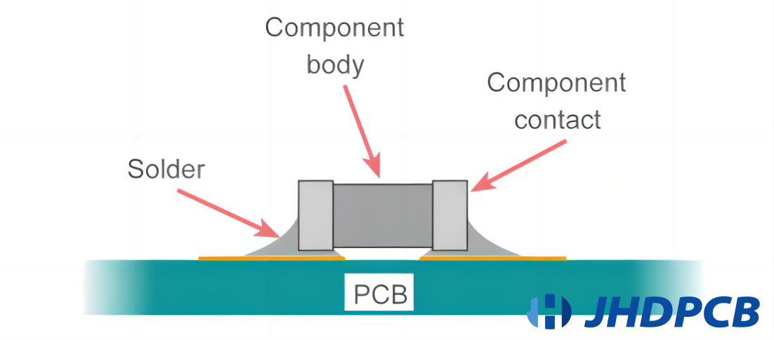
Surface mount components exhibit distinctions from their leaded counterparts. Rather than being engineered for interconnecting two points, SMT components are crafted for placement on a board and subsequent soldering.

The leads of SMT components do not traverse holes in the board, deviating from the anticipated configuration of traditional leaded components. Different package designs are customized for diverse component types. In a broad classification, these packaging styles can be divided into three main groups: passive components, transistors and diodes, and integrated circuits.The subsequent overview delves into these three classifications of SMT components:

Resistors, Capacitors, and Inductors:
SMT counterparts of resistors, capacitors, and inductors are characterized by compact, planar packages. These components are designed without protruding leads, contributing to a more streamlined and space-efficient arrangement on the Printed Circuit Board (PCB).

  • Resistors: surface mount technology resistors are typically rectangular in shape, and their planar design allows for efficient use of board space. They come in various resistance values and power ratings.
  • Capacitors: SMT capacitors are often flat and can be found in a variety of package styles. The absence of leads simplifies their integration into densely populated PCBs.
  • Inductors: SMT inductors are designed in compact packages, facilitating their incorporation into space-constrained electronic devices. The absence of protruding leads enhances the overall compactness of the design.

1.Small Signal Transistors and Diodes:
SMT iterations of small signal transistors and diodes come in various package styles, including SOT-23 and SOD-323. These packages are meticulously designed to accommodate the diminutive size of these semiconductor devices while enabling convenient surface mounting.

  • SOT-23: The compact outline of this transistor package is extensively utilized for small signal transistors. Featuring three leads, it is commonly employed in scenarios where spatial constraints play a pivotal role.
  • SOD-323: This small outline diode package is compact and is commonly used for small signal diodes. It is appropriate for situations where conserving space is essential.

2.Power Transistors and Diodes:
For applications requiring higher power, prevalent SMT packages such as DPAK and TO-252 are employed. These packages are formulated to dissipate heat efficiently while maintaining a compact footprint.

  • DPAK (TO-252): This surface mount package is often used for medium to high-power transistors and diodes. Its configuration enables efficient dissipation of heat, rendering it applicable for power-related uses.
  • TO-252: Similar to DPAK, TO-252 is a package commonly used for power transistors and diodes.It achieves equilibrium between a condensed form factor and effective heat dispersion.

Quad Flat Packages (QFP), Ball Grid Arrays (BGA), and Chip-on-Board (COB):
ICs in SMT are frequently housed in planar packages like QFP or BGA, offering a high pin count within a petite form factor. COB entails directly affixing a semiconductor die to the PCB, conserving space, and facilitating a low-profile design.

  • QFP (Quad Flat Package): QFP is a planar, square, or rectangular casing with pins distributed along all four edges.It allows for a high pin count and is commonly used for microcontrollers and processors.
  • BGA (Ball Grid Array): BGA packages have solder balls on the bottom, providing a high-density interconnection. They are widely used for integrated circuits with high pin counts, such as graphics processors and chipsets.
  • COB (Chip-on-Board): COB involves directly mounting and connecting a bare semiconductor die to the PCB. This approach is employed to save space and achieve a low-profile design.

In summary, the diverse package styles of SMT components cater to the specific requirements of distinct electronic elements, offering advantages in terms of space efficiency, automated assembly, and adaptability to contemporary design prerequisites.

In summary, the diverse package styles of SMT components cater to the specific requirements of distinct electronic elements, offering advantages in terms of space efficiency, automated assembly, and adaptability to contemporary design prerequisites.

What is the surface mount technology process?

In the initial phase, SMCs are chosen, and the PCB is designed. The board typically features flat copper pads, often plated with silver, tin-lead, or gold and lacking holes—referred to as solder pads. These solder pads provide support for the pins of various components, such as transistors and chips.

Another vital tool is the stencil, utilized to set a fixed position for the ensuing step of the process (solder paste printing), aligning with the predetermined positions of solder pads on the PCB.All materials to be utilized in the manufacturing process, including these, must undergo a thorough inspection for any defects.

This stage holds crucial significance within the Surface Mount Technology (SMT) process. Here, a printer is employed to administer solder paste utilizing a prepared stencil and a squeegee (a cleaning tool in printing) at an angle ranging from 45° to 60°. Solder paste, a putty-like amalgamation of powdered metal solder and adhesive flux, is applied. The flux functions as a temporary adhesive, securing surface mount components in position and simultaneously purifying soldering surfaces from impurities and oxidation.

The solder paste is specifically utilized to establish connections between the Surface Mount Components (SMCs) and the solder pads on the Printed Circuit Board (PCB). Ensuring that each pad receives the correct quantity of paste is imperative. Neglecting to perform this task may lead to ineffective connections when the solder undergoes liquefaction in the reflow oven. In the domain of electronic production, a reflow oven is an electronic heating apparatus employed in Surface Mount Technology (SMT) for attaching electronic components to printed circuit boards (PCBs).

Following the solder paste printing stage, surface mount technology machines, specifically pick-and-place machines, come into play for the precise positioning of components on the PCB. Utilizing either a vacuum or a gripper nozzle, each component is extracted from its packaging, and the placement machine accurately situates it according to its designated location. The PCB advances along a conveyor belt, and these swift and precise machines, capable of placing up to 80,000 individual components per hour, affix electronic components onto it.

Precision is paramount in this process, as any inaccuracies in component placement, once soldered, can incur significant costs and time-consuming rework.

Subsequent to the placement of Surface Mount Components (SMCs), the PCB proceeds to the reflow soldering oven, traversing through various zones to undergo the soldering process:

Preheat Zone: Serving as the initial zone, this section gradually raises the temperature of the board and attached components simultaneously. The temperature ascends at a rate of 1.0℃-2.0℃ per second until reaching 140℃-160℃.
Soak Zone: In this zone, the board is maintained at a temperature between 140℃ and 160℃ for 60-90 seconds.
Reflow Zone:The boards subsequently progress through a region where the temperature rises at a rate of 1.0℃-2.0℃ per second, ultimately reaching a peak within the range of 210℃-230℃. This specific melting point enables the amalgamation of the tin within the solder paste, effectively connecting the leads of the component to the pads on the PCB.Concurrently, the surface tension of the molten solder keeps the components securely in place.
Cooling Zone: Serving as the concluding section, this zone ensures that the solder solidifies upon exiting the heating zone, preventing joint defects.
For double-sided printed circuit boards, these procedures might be reiterated, utilizing either solder paste or adhesive to anchor the Surface Mount Components (SMCs) in place.

Following the soldering process, the circuit board undergoes thorough cleaning and meticulous inspection for any imperfections. In the event of any identified flaws, necessary repairs are carried out before the final product is placed in storage.
Multiple methods are utilized to inspect Surface Mount Technology (SMT), including magnification tools, Automated Optical Inspection (AOI), flying probe testing, X-ray inspection, and various others.Machine-based methods are favored over manual inspection, ensuring rapid and precise results instead of relying on human observation.

What is the difference between SMT and Through-Hole Technology?

surface mount technology vs through hole


Component Mounting:

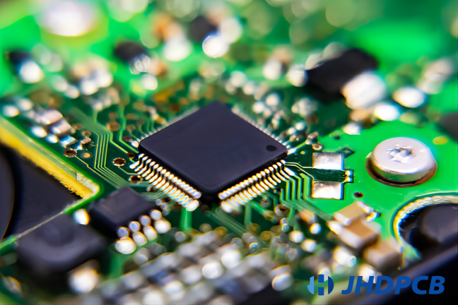
SMT:Components are affixed directly onto the surface of the PCB through the utilization of petite, flat leads or direct soldering onto pads present on the PCB.
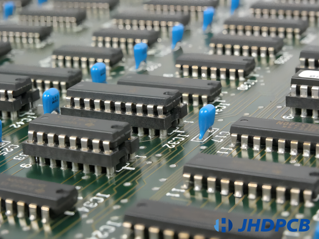
Through-Hole: Components possess wire leads that traverse openings in the PCB and are soldered on the reverse side.

Construction and Size:

SMT: Components in SMT are generally smaller and lighter, enabling higher component density and smaller PCBs.
Through-Hole: Through-Hole components are typically larger, and the holes required for their leads can limit available PCB space.

Assembly Process:

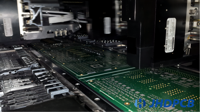
SMT: SMT assembly is highly automated, utilizing pick-and-place machines for precise component positioning and reflow ovens for soldering.
Through-Hole: Assembly can be manual or automated. Components are inserted into holes, and soldering is typically done through wave soldering or manual methods.

Mechanical Strength:

SMT: SMT components are soldered directly to the PCB surface, providing good mechanical strength and vibration resistance.
Through-Hole: Through-Hole components gain mechanical strength from leads passing through the PCB, but the reliance on leads may make them more susceptible to mechanical stress.

Cost:

SMT: Generally more cost-effective for high-volume production due to automation and smaller component size.
Through-Hole: May be more time-consuming and expensive, especially for large and complex boards, often involving manual labor.

Design Flexibility:

SMT: Offers greater design flexibility, particularly suitable for compact, high-density designs.
Through-Hole: Preferred for designs prioritizing robustness and repairability, or for components not available in SMT packages.

Repair and Rework:

SMT: Reworking SMT components can be more challenging due to the smaller size and densely populated boards.
Through-Hole: Through-Hole components are generally easier to rework and repair.

Industry Trends:

SMT: Widely adopted in modern electronics manufacturing, especially for high-volume production and miniaturized devices.
Through-Hole: Still used in specific applications, especially where reliability and repairability are critical, or for specialized components.

In contemporary electronics manufacturing, a combination of both SMT and Through-Hole technologies, known as mixed-technology assembly, is often utilized to optimize the benefits of each approach for different components on a single PCB.

Characteristic Through-Hole Surface Mount
Finish Type Non-planar HASL most common Planar finish (ENIG, Immersion Silver, OSP)
Lead Insertion Method Hole required Components mount to surface pads, no hole
Assembly Configuration Rare 2-sided assembly Common 2-sided assembly
Lead Spacing Typically 0.100” or greater 0.0157” spacing (0.0197” common)
Assembly Method Manual assembly Automated assembly
Soldering Manual or automated Typically automated
Stencil Requirement Not required Required unless small lot, simple PCB
Vias in Pads Not possible Possible
Laminate Temperature Standard temperature (130C Tg) High-temperature (170C Tg)
Test Points Through-hole Through-hole or SMT
Component and Circuit Density Lower density Greatly increased density
PCB Footprint Larger Minimal
Rework Complexity Relatively simple Some rework more involved
Warp and Twist Tolerance Moderate tolerable More critical for assembly
Fiducial Pads Requirement Not required Required for automated pick-and-place equipment

Advantages and Disadvantages of Surface Mount Technology

In the world of electronic manufacturing, Surface Mount Technology (SMT) has its pros and cons. On the positive side, it allows for automated assembly, boosting efficiency and reducing labor costs. However, the downside includes challenges in rework and repair due to the small size of SMT components. Let’s delve into surface mount technology advantages and disadvantages in electronic production.

Advantages of Surface Mount Technology (SMT):

  1. Space Efficiency:
    SMT enables the creation of more diminutive and space-efficient electronic devices by virtue of the diminished dimensions of components and the capability to directly affix them onto the PCB surface.
  2. Higher Component Density:
    SMT allows for an augmented density of components on a PCB, resulting in heightened functionality within a more confined area.
  3. Improved Electrical Performance:
    Shorter lead lengths and reduced parasitic effects contribute to better electrical performance, including higher speed and lower electromagnetic interference.
  4. Automated Assembly:
    SMT facilitates automated assembly processes, where surface mount technology assembly plays a pivotal role, leading to higher production efficiency, lower labor costs, and increased consistency in component placement.
  5. Cost Efficiency for High Volume Production:
    In high-volume production, SMT is generally more cost-effective due to automated processes, reduced material waste, and faster assembly times.
  6. Enhanced Thermal Performance:
    The smaller size and closer proximity of SMT components to the PCB surface allow for more efficient heat dissipation.
  7. Compatibility with Advanced Technologies:

    SMT is well-suited for advanced technologies such as miniaturization, high-frequency applications, and the integration of complex electronic functionalities.

Disadvantages of Surface Mount Technology (SMT):

  1. Rework Challenges:
    Reworking or repairing SMT components can be more challenging due to their small size and the densely populated nature of modern PCBs.
  2. Initial Setup Costs:
    The initial setup costs for implementing SMT processes, including the purchase of equipment and training of personnel, can be relatively high.
  3. Limited Suitability for Power Components:
    SMT may not be as suitable for high-power components that generate significant heat, as the reduced size can hinder effective heat dissipation.
  4. Component Availability:
    Some components may not be available in SMT packages, limiting the flexibility of design choices.
  5. Dependence on Surface Finish Quality:
    The quality of the surface finish on the PCB is crucial for successful SMT soldering, and poor surface finishes can lead to soldering defects.
  6. Susceptibility to Damage:
    SMT components can be more susceptible to damage during handling and rework due to their smaller size and delicate nature.
  7. Reliability Concerns in Extreme Environments:
    In extreme environmental conditions, such as high temperatures or vibrations, the reliability of solder joints in SMT components may be a concern compared to Through-Hole components.

It’s important to note that the choice between SMT and other assembly technologies depends on the specific requirements of the application and the desired balance between size, performance, and ease of manufacturing. Many modern electronic devices use a combination of SMT and Through-Hole technologies in a mixed-technology approach to leverage their respective advantages.

Guidelines for SMT component placement

Guidelines for SMT component placement

Placement of components in Surface Mount Technology (SMT) is a pivotal stage in the electronic manufacturing process, and accuracy in positioning is imperative for the operational effectiveness and dependability of the end product.Here are some guidelines for SMT component placement, aligning with surface mount technology principles and practice:

  1. Accurate Design Information:Ensure that the design information, including the component placement data, is accurate and up-to-date. This information is typically provided in the PCB layout design files.
  2. Use a Pick-and-Place Machine:Employ automated pick-and-place machines for SMT component placement. These machines can handle high volumes, provide precise placement, and contribute to the overall efficiency of the assembly process.
  3. Component Orientation:Pay careful attention to the orientation of each component. Ensure that polarized components, such as capacitors and diodes, are placed in the correct orientation to meet the electrical requirements.
  4. Check Component Packages:Verify that the components being used match the package specified in the design. Different packages may have different dimensions, and accuracy in matching the components to the design is crucial.
  5. Component Inspection:Inspect components before placement to ensure there are no defects, such as bent leads or damaged packages. Damaged components can lead to unreliable solder joints and potentially affect the functionality of the circuit.
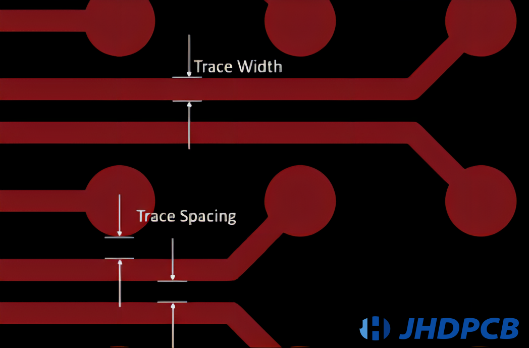
  6. Optimal Component Spacing:Follow recommended guidelines for component spacing to avoid issues such as solder bridging or insufficient solder. Adequate spacing also facilitates easier inspection and maintenance.
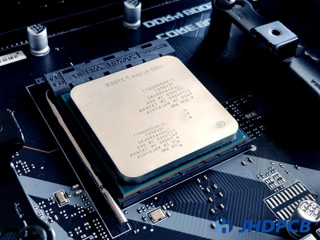
  7. Consider Thermal Considerations:Take into account the thermal characteristics of components during placement. Components generating significant heat, such as power components or microprocessors, should be placed to optimize heat dissipation and prevent overheating.
  8. Group Components Logically:Group components logically based on their functions. This can aid in troubleshooting and maintenance later on. For example, place related components, such as those forming a specific circuit block, close to each other.
  9. Adhere to Design Rules:Follow the design rules specified for your PCB layout. These rules may include specific guidelines for component placement to ensure signal integrity, reduce electromagnetic interference, and optimize the performance of the circuit.
  10. Quality Control Measures:Implement quality control measures, such as Automated Optical Inspection (AOI), after component placement. AOI can identify issues such as misaligned components or solder defects, ensuring the overall quality of the assembly.
  11. Documentation and Traceability:Maintain accurate documentation of the component placement process. This includes keeping records of the pick-and-place machine settings, component reel information, and any adjustments made during the placement process. This documentation aids in traceability and facilitates future modifications or repairs.

By adhering to these guidelines, manufacturers can enhance the accuracy, reliability, and efficiency of the Surface Mount Technology component placement process in electronic manufacturing.

What are the applications of Surface Mount Technology?

applications of Surface Mount Technology

Surface Mount Technology (SMT) has become a cornerstone in the manufacturing of electronic devices, contributing to the widespread functionality and compact designs seen in various products. The versatility and efficiency of SMT enable its application across a diverse range of electronic devices, including:

  1. Automotive Electronics:SMT plays a crucial role in the production of automotive electronic systems, controlling everything from engine performance to in-car entertainment.
  2. Medical Devices:Within the medical domain, Surface Mount Technology (SMT) is employed in the production of instruments such as patient monitoring systems, diagnostic apparatus, and medical imaging devices.
  3. Communication Devices:SMT is integral to the production of communication devices like routers, modems, and networking equipment, ensuring reliable connectivity in modern homes and offices.
  4. Gaming Consoles:Gaming consoles, such as PlayStation and Xbox, incorporate densely populated circuit boards made possible by SMT for enhanced gaming experiences.
  5. Wearable Technology:The condensed and lightweight characteristics of SMT components render them well-suited for incorporation into wearable gadgets, encompassing smartwatches, fitness trackers, and health monitoring devices.
  6. Industrial Equipment:SMT is widely used in the manufacturing of industrial electronic equipment, ranging from control panels and automation systems to sensors and measurement devices.
  7. Aerospace and Defense Systems:The reliability and miniaturization benefits of SMT make it indispensable in aerospace and defense applications, where space and weight constraints are critical considerations.
  8. Home Automation Devices:Devices that form the backbone of home automation systems, such as smart thermostats, security cameras, and smart doorbells, often feature SMT components for their compact and efficient designs.
  9. Audio Equipment:High-quality audio devices, including soundbars, speakers, and audio receivers, leverage SMT for efficient circuitry that enhances audio performance.
  10. Renewable Energy Systems:Surface Mount Technology (SMT) is utilized in the manufacturing of electronic components for renewable energy systems, including solar inverters and control systems for wind turbines.
  11. Consumer Electronics:Beyond the listed items, a vast array of consumer electronics, including MP3 players, electronic readers, and portable gaming devices, owe their compact designs and advanced functionalities to SMT.

The adaptability and scalability of SMT continue to drive innovation in the electronics industry, enabling the creation of more sophisticated and interconnected devices that have become integral to our daily lives. As technology evolves, SMT remains a fundamental enabler of progress in electronic design and manufacturing. 

Frequently Asked Questions of SMT

Surface Mount Technology (SMT) is an electronic manufacturing technique where electronic components, encompassing SMT elements, are affixed directly onto the surface of a printed circuit board (PCB). This is in contrast to through-hole technology, where components have leads inserted into holes in the PCB. SMT allows for smaller components and a more automated manufacturing process.

SMT components are mounted onto a PCB during the assembly process using a pick-and-place machine. This automated machine precisely picks up SMT components and places them onto designated locations on the PCB according to the assembly design. This approach is effective, facilitating increased component density and reduced overall dimensions of PCBs.

Reflow ovens play a crucial role in the Surface Mount Technology (SMT) process, specifically in reflow soldering. Following the placement of SMT components on the PCB, the assembly undergoes a reflow oven process. The oven elevates the temperature of the PCB, inducing the liquefaction of the solder paste and the formation of solder joints connecting the components to the PCB. This ensures secure and reliable electrical connections.

Automated Optical Inspection (AOI) is a quality control process in electronic manufacturing, particularly in Surface Mount Technology (SMT). AOI systems use cameras and image processing to inspect solder joints, component placement, and other aspects of the PCB assembly. This technology helps identify defects or anomalies, ensuring that the SMT assemblies meet the required quality standards.

Surface Mount Technology (SMT) provides numerous benefits in comparison to through-hole technology, such as the utilization of smaller components, increased component density, and a manufacturing process that is more automated. SMT enables the production of smaller and lighter electronic devices, improved signal integrity, and increased efficiency in the overall manufacturing process. The transition to SMT has been a significant advancement in electronic manufacturing.

Surface mount technology equipment commonly used in soldering and surface mount technology (SMT) includes soldering irons, reflow ovens, solder paste dispensers, and pick-and-place machines. These tools are essential for the precise placement and soldering of surface mount components onto PCBs. Soldering irons are utilized for manual soldering tasks, while reflow ovens play a crucial role in the automated reflow soldering process, ensuring a controlled environment for melting solder paste and forming reliable connections. Solder paste dispensers are responsible for accurately applying solder paste to PCBs before component placement, and pick-and-place machines automate the precise positioning of components on the board, enhancing efficiency and accuracy in the SMT assembly process.

In conclusion, Surface Mount Technology (SMT) stands as a driving force in the realm of electronic manufacturing, reshaping the landscape of modern devices with its precision and efficiency. The ability to seamlessly integrate components onto printed circuit boards has not only enhanced the performance of electronic devices but has also fostered innovation across industries.

At JHDPCB, we recognize the pivotal role that SMT plays in the development of cutting-edge technology. With a commitment to excellence and state-of-the-art facilities, we pride ourselves on offering superior PCB manufacturing services, including advanced SMT capabilities. At JHDPCB, our team is committed to delivering customized solutions that adhere to the most stringent industry benchmarks. Whether in the domains of consumer electronics, telecommunications, or beyond, our expertise ensures that your PCB requirements are met with precision and reliability. Trust in JHDPCB for quality SMT services, as we continue to be a trusted partner in transforming electronic designs into reality.

Get a PCB Quote Now

Open high-quality PCB manufacturing services in JHDPCB

Leave a Comment