An AC source powering a load

Measurement and Characteristics of AC Voltage on PCB

directory

At JHDPCB, we specialize in designing and producing high-quality PCBs for AC power applications. With our experienced team, state-of-the-art facilities, and rigorous quality control processes, we deliver reliable and efficient solutions for power generation, distribution, and control. Expect exceptional customer service, timely delivery, and cost-effective solutions that meet your performance, reliability, and safety needs. Let’s explore the world of AC power together and discover how JHDPCB can be your trusted partner.

What is ac voltage?

Alternating current, commonly known as AC, refers to the movement of electric charge that cyclically changes its direction. It commences from zero, rises to a peak, diminishes to zero again, reverses its course, reaches a maximum in the opposite direction, returns to its initial value, and perpetually repeats this pattern. The duration between two consecutive cycles is recognized as the period, the quantity of cycles per second is referred to as the frequency, and the highest value in either direction is denoted as the amplitude of the alternating current. Low frequencies, such as 50 and 60 hertz, are used for domestic and commercial power, while higher frequencies, such as 100 megahertz in television and several thousand megahertz in radar or microwave communication, are employed. Cellular telephones operate at frequencies of approximately 1 gigahertz.

The potential distinction between the optimistic and negative terminals is measured in volts (V). Consequently, the expression AC voltage is employed to indicate the magnitude of the voltage between the terminals wherein the alternating stream passes.

When depicted on a graph, AC voltage follows a sinusoidal waveform. Within one comprehensive cycle, the voltage starts from 0V, increases to its utmost value, traverses back through 0V to its negative maximum, and returns to 0V. As AC voltage perpetually fluctuates throughout the cycle, it is frequently denoted in terms of its peak value (Vpeak) and its root-mean-square value (Vrms).

Vpeak corresponds to the pinnacle extent of the sinusoidal waveform, whereas Vrms is computed using the subsequent equation:

Vrms = Vpeak x 0.7071

Vrms is alternatively known as Vac and signifies the effective voltage delivered by DC. In the United States, the mains supply offers 120 Vac, while in the UK, it is 230 Vac.

How Is AC Voltage Generated?

AC voltage is produced through a phenomenon known as electromagnetic induction. The generation of AC voltage involves a series of stages:

  1. Creation of Rotating Magnetic Field: In order to generate AC voltage, a rotating magnetic field is established. This can be accomplished using an alternator or generator. The alternator consists of a rotor (the rotating component) and a stator (the stationary component). When the rotor rotates, it creates a rotating magnetic field.
  2. Faraday’s Prnciple of Electromagnetic Induction: As per Faraday’s principle, the occurrence of a shifting magnetic field prompts the generation of an electromotive force (EMF) within a conductor. When the rotating magnetic field intersects with the coils of the stator, it generates an altering magnetic flux. This varying magnetic field induces an alternating current voltage in the stator windings.
  3. Wire Coils: The stator windings consist of multiple wire coils. Typically, these windings are constructed using copper or aluminum materials and are wrapped around a core composed of iron. The number of turns in the wire coils affects the magnitude of the induced voltage.
  4. Magnetic Flux Reversal: As the rotor continues to rotate, the direction of the magnetic field periodically reverses. The reversal of the magnetic field results in the generation of an alternating current in the windings of the stator. The frequency of the generated AC voltage depends on the rotational speed and the number of magnetic pole pairs on the rotor.
  5. Output Terminals: The produced AC voltage can be accessed at the terminals designated as the output of the generator.

It is worth noting that the frequency of the produced AC voltage is established by the design and rotational speed of the generator. In the majority of power systems, the standard frequency is either 50 or 60 Hz, depending on the specific geographical region.

AC Alternators

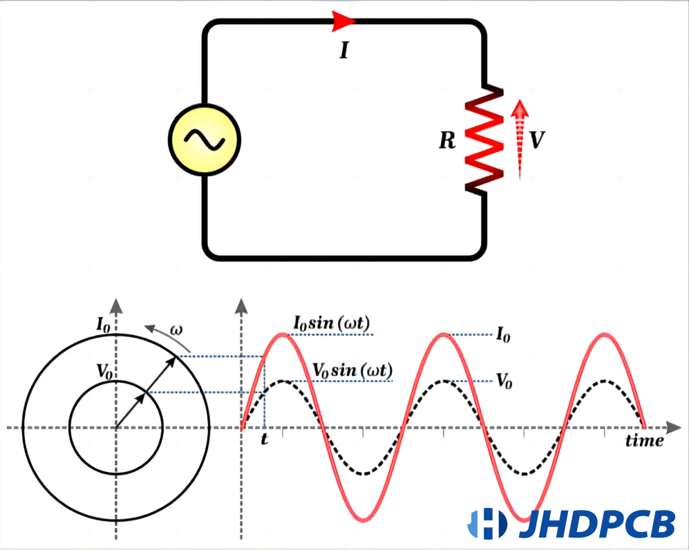
If a device is designed to spin a magnetic field around a group of immobile wire coils using the rotation of a shaft, an AC voltage will be generated across those wire coils as the shaft turns, following Faraday’s principle of electromagnetic induction.
This forms the fundamental principle of operation for an AC generator, commonly known as an alternator. Please refer to the diagram provided below.

Alternator operation

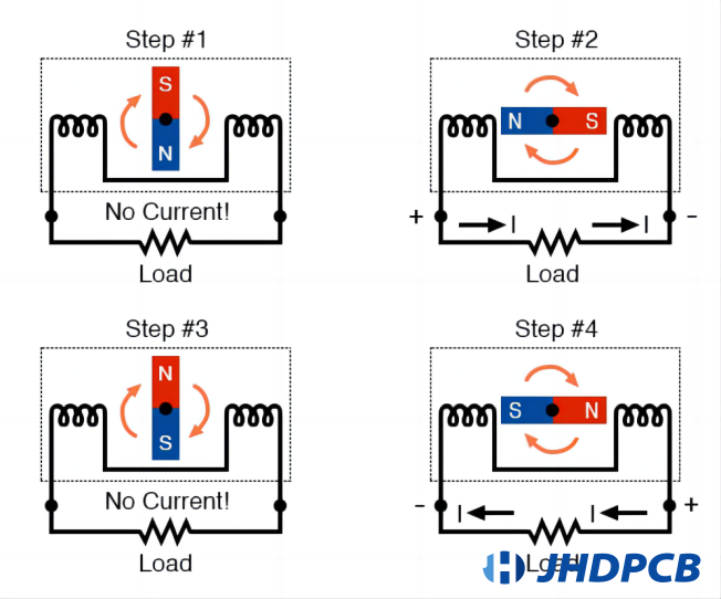
Observe the phenomenon where the voltage polarity across the wire coils changes when the opposite poles of the rotating magnet come into proximity.
When the generated voltage is connected to a load, this alternating polarity will give rise to an alternating current flowing in the circuit. The rotational speed of the alternator’s shaft directly influences the rate at which the magnet rotates, resulting in an AC voltage and current that switch their directions more frequently within a given time frame.
While DC generators operate based on the same fundamental principle of electromagnetic induction, their construction is comparatively more intricate than that of AC generators.
In essence, the production of AC voltage entails the rotation of a magnetic field within a generator, thereby causing the induction of an alternating current in the wire windings of the stator.
In summary, the generation of AC voltage involves the rotation of a magnetic field within a generator, which in turn induces an alternating current in the wire coils of the stator. This fundamental principle of electromagnetic induction serves as the foundation for the production of AC power.

How to measure ac voltage?

To gauge AC voltage, one can employ a device known as a voltmeter. Here are the steps to measure AC voltage using a voltmeter:

  1. Ensure that the voltmeter being utilized is suitable for measuring AC voltage. The majority of digital multimeters (DMM) are equipped with the capability to measure voltage, both AC and DC.
  2. Adjust the voltmeter’s range to the appropriate AC voltage range. For instance, if you expect the AC voltage to be approximately 120 volts, select the AC voltage range closest to that value.
  3. Establish connections between the test leads of the voltmeter and the circuit or device from which you want to measure the AC voltage. Usually, the red lead is attached to the positive terminal or a point of higher potential, while the black lead is connected to the negative terminal or a point of lower potential.
  4. Verify that the connections are secure and there are no loose contacts between the test leads and the circuit.
  5. Activate the voltmeter and observe the display, which should indicate the measured AC voltage value in volts.
  6. If necessary, fine-tune the range setting of the voltmeter to obtain a more accurate reading. Select a higher range if the displayed value is close to the maximum range of the voltmeter, or select a lower range if the displayed value is close to the minimum range.
  7. Make a note of the measured AC voltage value for reference or further calculations.
  8. Once the measurement is complete, power off the voltmeter and disconnect it from the circuit.

It is crucial to acknowledge that AC voltage measurements may fluctuate over time due to the nature of alternating current. Therefore, it is generally recommended to take multiple measurements to ensure accuracy and uniformity.Moreover, always adhere to safety protocols and employ suitable personal protective gear when dealing with electrical systems.

Analysis of AC voltage measurements

  1. AC voltage sources exhibit fluctuations:
    AC voltage measurements can experience variability due to the fluctuations in AC voltage across power distribution systems. These fluctuations can arise from factors such as variations in power demand, changes in generation capacity, or fluctuations in distribution line impedance. These fluctuations can lead to differences in the recorded AC voltage at various locations within the system.
  2. Lower voltage readings:
    When measuring AC voltage, if the recorded value deviates from the anticipated value, it is more likely to be below the normal range. This can occur due to voltage attenuation in transmission and distribution lines, insufficient transformer capacity, or heightened power demand during peak periods. Inadequate voltage can have a negative impact on the operation and effectiveness of electrical devices and appliances.
  3. Voltage tolerance range:
    Generally, AC power systems adhere to a specific tolerance range for measured voltage. The acceptable range may vary depending on regional or national regulations and standards. For instance, in many power systems, the permissible voltage range is typically specified to be within -10% to +5% of the nominal voltage. This range ensures that the voltage remains within acceptable limits for proper operation of electrical devices.
  4. Variation in voltage measurements:
    Voltage measurements can vary across different locations within an AC power system. This is due to voltage drop occurring as current traverses through transmission and distribution lines, as well as fluctuations in load conditions at various points. Voltage measurements taken closer to the power source or substation generally exhibit less variation compared to measurements taken farther away or at the end of lengthy distribution lines.
System Voltage Ranges
Supply Service Range Point of Use Range
Adhesive Acceptable Satisfactory Acceptable
120, 1Φ 114 – 126 110 – 127 110 – 126 106 – 128
120/240, 1Φ 114/228 – 126/252 110/220 – 127/254 110/220 – 126/252 106/212 – 127/254
120/208, 3Φ 114/197 – 126/ 110/191 – 127/220 110/191 – 126/218 106/184 – 127/220
120/240, 3Φ 114/228 – 126/252 110/220 – 127/254 110/220 – 126/252 106/212 – 127/254
277/480, 3Φ 263/456 – 291/504 254/440 – 293/508 254/440 – 291/504 264/424 – 293/508

Monitoring and analyzing AC voltage measurements play a crucial role in upholding a reliable power supply, guaranteeing the secure functioning of electrical equipment, and detecting any possible anomalies or irregularities within the power system. Systematic monitoring aids utilities and engineers in promptly identifying and resolving voltage-related issues, facilitating timely intervention and mitigation measures.

What is the symbol for ac voltage?

The ac voltage symbol on a multimeter is V~, where V represents voltage, and the ~ sign indicates alternating current (which reverses direction periodically). AC voltage refers to the voltage of an alternating (changing) current.

It is important to note that the household power supply is characterized by AC voltage, while batteries provide DC voltage.

In certain earlier models of multimeters, the dial or knob may be labeled with “VAC” to indicate AC voltage instead of the symbol “~”. The symbols are typically displayed on the surface of the multimeter surrounding the dial or knob. To measure the AC voltage of a circuit, you need to adjust the dial or knob to the position marked with the symbol “V~”.

Multimeters have the capability to measure AC voltage within the range of 200 to 600 volts. Since household AC supplies typically operate at higher levels such as 120 or 240 volts, the multimeter is equipped with a higher range (200 and 600 V) to test AC voltage.

On the other hand, DC voltage is provided by batteries and can vary from small to large values. Consequently, multimeters are designed with a range of millivolts to 600 volts for measuring DC voltage.

How to reduce ac voltage?

Imagine you have a primary power source that provides a voltage significantly higher than what is required for a specific section of a circuit, such as a chip. For instance, the circuit may be powered by a 9-volt battery, while the chip only necessitates 3 volts.

In such cases, there are multiple methods available to reduce the voltage, and one of the simplest and most cost-effective approaches involves the use of resistors. By employing resistors, we can establish a voltage divider circuit, allowing us to attain any desired voltage.

To comprehend the process of voltage reduction, it is necessary to grasp the underlying principles of voltage divider circuits, which will be explained in detail below. Through this technique, it becomes possible to decrease any given voltage to a desired level.

To halve the voltage, we can easily create a voltage divider circuit by using two resistors of equal magnitude (such as two 10KΩ resistors).

Halve the Voltage

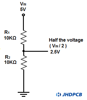
To achieve a voltage division of half, it is as simple as connecting two resistors of equal resistance in series and introducing a connection point (jumper wire) between the resistors. At this junction, the voltage will be precisely half of the supplied circuit voltage.

For instance, if the original voltage was 5V, it will now be reduced to 2.5V. The VCC is evenly divided into two halves.

You might not always desire a voltage division of exactly half, but you have the ability to adjust the voltage to any desired level by selecting appropriate resistor values for a voltage divider circuit.

For instance, let’s say your circuit is powered by a 5V source, but you specifically require a voltage of 3V for a particular component within the circuit. How can you achieve this transformation from 5 volts to 3 volts?

The solution lies in implementing a voltage divider circuit with correctly chosen resistor values. But how do you calculate these values?
The formula provided below allows you to determine the voltage that appears across the resistor labeled as R2.

determine the voltage that appears across the resistor labeled as R2

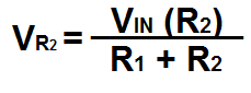
However, in its original form, this formula does not directly provide the necessary information for determining the required resistor value R2 to achieve a specific voltage. By rearranging this formula and solving for R2, we obtain the following alternative formula.

alternative formula

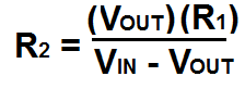
This formula provides us with the means to select the appropriate resistor value needed to achieve any desired voltage.

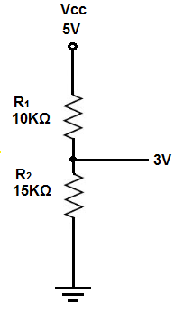
Returning to our circuit scenario, where we have a 5-volt source and aim to obtain 3 volts from it, we can employ the aforementioned formula. Assuming we take a 10KΩ resistor as our R1 value, plugging in the given values yields R2 = (V)(R1) / (VIN – V) = (3V)(10KΩ) / (5V – 3V) = 15KΩ. Hence, we can utilize a 15KΩ resistor for R2, while setting R1 to be 10KΩ.

circuit scenario of R1 to be 10KΩ

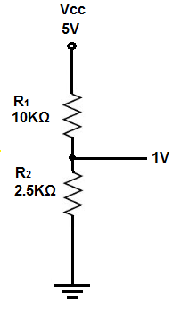
Let’s consider another example using the same circuit configuration where we have a 5V input voltage but require an output voltage of only 1V. If we choose a 10KΩ resistor as our R1, substituting the given values into the formula, we obtain R2 = (V)(R1)/(VIN – V) = (1V)(10KΩ)/(5V – 1V) = 2.5KΩ. Therefore, in this scenario, we can utilize a 2.5KΩ resistor as our R2 resistor, while setting R1 to be 10KΩ.

5V input voltage but require an output voltage of only 1V


Hence, it becomes evident that achieving any desired voltage is a straightforward task using a resistor voltage divider circuit.

To validate the calculations performed for voltage dividers, you may refer to the Voltage Divider Calculator. This instrument enables you to validate the precision and accuracy of your calculations. The Voltage Divider Calculator is capable of computing voltage division from 2 resistors up to 10 resistors configured in a voltage divider circuit.

Application of Alternating Current.

AC voltage finds widespread utilization in diverse industries and everyday scenarios. Below are several typical applications of AC:

  1. Power Generation and Distribution:
    The majority of electricity generation facilities, such as thermal, hydroelectric, and nuclear plants, generate electrical power in the form of AC. AC is the preferred choice for transmitting electricity over long distances due to its capability of being easily adjusted in voltage using transformers. It facilitates the efficient dissemination of electricity from power plants to households, commercial establishments, and industrial sectors.
  2. Residential and Commercial Power Supply:
    AC serves as the main electricity source for residential and commercial structures. It supplies power to lighting systems, HVAC systems, household appliances, personal computers, televisions, and other electronic devices utilized in dwellings, workplaces, educational institutions, and retail outlets.
  3. Electric Motors: 
    AC motors find extensive usage across diverse sectors, encompassing industrial equipment, domestic appliances, transportation, and HVAC systems. AC induction motors, in particular, enjoy widespread use owing to their durability, dependability, and economical nature. They facilitate the conversion of electrical energy into mechanical energy, thereby enabling the operation of pumps, fans, compressors, conveyors, and other machinery.
  4. Lighting: 
    AC is employed for illumination in residential areas, commercial spaces, roadways, sports arenas, and other settings. AC voltage is provided to fluorescent tubes, traditional bulbs, halogen lights, and LED lighting fixtures. AC provides benefits such as seamless operation without flickering, effortless dimming functionalities, and compatibility with diverse lighting technologies.
  5. Electronics and Appliances: 
    AC is employed to energize an extensive array of consumer electronics and domestic appliances, including fridges, air conditioners, TVs, washing machines, computers, and audio systems. Within these devices, AC power is converted to DC (Direct Current) using rectifiers or power supplies, enabling the functioning of their internal circuits.
  6. Electric Vehicle Charging:
    With the increasing adoption of electric vehicles, charging stations make use of AC power for vehicle charging. The AC power sourced from the grid is transformed into DC power via onboard chargers installed in the vehicles. AC charging can be performed at different power levels, including Level 1 (conventional household socket), Level 2 (dedicated charging unit), and Level 3 (rapid charging stations).
  7. Integration of Renewable Energy: 
    Alternating current (AC) is utilized in the integration of renewable energy sources such as solar and wind power into the electric grid. Solar panels and wind turbines produce DC power, which is transformed into AC power through inverters prior to being injected into the power grid for distribution.
  8. Industrial Processes: 
    AC power finds widespread application in industrial procedures, encompassing manufacturing, chemical processing, mining, and water purification. It supplies energy to motors, pumps, compressors, conveyor networks, and other crucial machinery required for industrial activities.
  9. Medical Equipment:
    AC power plays a critical role in healthcare facilities, serving various purposes such as energizing diagnostic apparatus, surgical instruments, life-sustaining systems, imaging devices, and patient surveillance equipment.
  10. Research and Testing: 
    AC power is utilized in laboratories and research establishments for conducting experiments, testing electrical apparatus, and simulating as well as analyzing the behavior of power systems under diverse circumstances.

These are merely a handful of instances showcasing the extensive range of applications for AC power. The adaptability, effectiveness, and seamless transmission and conversion capabilities establish AC as the favored option for the majority of electricity-centric purposes across the globe.

The characteristics of AC.

AC, also known as alternating current, refers to a form of electric current that cyclically alters its direction. It is widely employed for transmitting and distributing power in electrical systems. Here are the traits, benefits, and drawbacks of AC:

Characteristics of AC:

  1. Cyclical Fluctuation: Alternating current (AC) demonstrates periodic variation, oscillating between cycles of positive and negative values.
  2. Frequency: AC current is characterized by its frequency, denoting the number of cycles per second. In many nations, the commonly adopted frequency is either 50 or 60 Hz.
  3. Voltage Level: AC voltage can be conveniently adjusted using transformers, enabling efficient transmission and distribution across extensive distances.
  4. Waveform: AC current possesses a sinusoidal waveform, signifying its adherence to a smooth and regular pattern.
  5. Power Factor: AC systems incorporate a power factor, which denotes the ratio between real power and apparent power. The power factor influences the efficiency of electrical systems.

Advantages of AC:

  1. Efficient Transmission: AC voltage can be effortlessly elevated to high levels using transformers, facilitating efficient long-distance transmission. This diminishes power losses during the transmission process.
  2. Power Generation: The majority of power plants generate AC power, rendering it compatible with existing infrastructure.
  3. Voltage Regulation: AC systems can be regulated through the utilization of transformers and voltage regulators, enabling stable and controlled voltage levels.
  4. Motor Operation: AC motors find extensive usage in diverse applications owing to their simplicity, dependability, and capacity to operate at variable speeds.
  5. Safety: AC systems pose lower risks of electric shock compared to DC systems, as the current periodically alters its direction, reducing the likelihood of sustained muscle contractions.

Disadvantages of AC:

  1. Elaborate Circuitry: AC circuits often necessitate intricate circuitry, including transformers, capacitors, and inductors, which can augment the intricacy and expenditure of electrical systems.
  2. Power Factor Challenges: AC systems may encounter power factor challenges, leading to loss of reactive power and reduced efficiency. Rectification measures for power factor correction may be necessary to address this issue.
  3. Limited DC Utilization: Certain devices and applications, such as electronic gadgets and specific industrial processes, necessitate direct current (DC). The conversion of AC to DC can introduce additional losses and complexity.
  4. Skin Effect: When operating at high frequencies, alternating current has a tendency to concentrate closer to the outer surface of conductors, resulting in increased resistance and power losses.
  5. Electromagnetic Interference: AC systems have the potential to generate electromagnetic interference (EMI) that might affect vulnerable electronic devices and communication systems. Supplementary precautions, like shielding and filtering, may be obligatory to mitigate EMI.

In general, AC offers a plethora of advantages, including effective transmission, voltage regulation, and compatibility with established infrastructure. Nevertheless, it is not without its drawbacks, such as intricate circuitry, power factor challenges, and limitations in certain applications. The selection between AC and DC hinges on the particular needs and limitations of the electrical system or application.

In conclusion, AC voltage is generated through the phenomenon of electromagnetic induction, where a fluctuating magnetic field induces an alternating current in a conductor. Power plants employ generators to generate AC voltage, which is subsequently distributed to various electrical devices via transformers and transmission lines.

At JHDPCB, we are a well-regarded manufacturer of printed circuit boards (PCBs) equipped with cutting-edge capabilities. Our advanced equipment and proficiency enable us to deliver PCB products of superior quality. Our highly skilled team is devoted to meeting customer specifications and providing optimal solutions. If you require PCB manufacturing and assembly services, please do not hesitate to reach out to us. We offer a complimentary file review service, where we comprehensively assess and test your design’s bill of materials (BOM) to ensure safety and suitability, thereby avoiding unnecessary losses. We are committed to providing outstanding service and look forward to working together with you.

Get a PCB Quote Now

Open high-quality PCB manufacturing services in JHDPCB

Leave a Comment