As the core material of PCB, the three main raw materials for the production of CCL include glass fiber cloth, epoxy resin and copper foil, and PCB relies on them to realize the functions of conduction, insulation and support. Among them, glass fiber cloth and epoxy resin are often used as prepregs.
There are instances where it becomes necessary to reinforce specific sections of a flexible circuit board or FPC with stiffeners. PCB stiffeners are utilized to add rigidity to certain areas of the board, making it easier to incorporate interconnects or solder components to these stiffer regions.
It’s important to note that PCB stiffeners do not serve as electrical components of the PCB. Instead, their purpose is to provide mechanical support to the printed circuit board during the assembly process. Additionally, PCB stiffeners offer benefits such as increased abrasion resistance, reinforcement of solder joints, and improved handling of the board for automated pick-and-place processes.
It should be acknowledged that utilizing stiffeners on a small panel can result in wastage of the square area. However, connector selection often necessitates this approach due to the limitations of certain connectors.
Polyamide (PI) Stiffeners, FR4 Stiffeners, and Stainless Steel Stiffeners are three commonly employed types of PCB stiffeners. These materials are particularly useful in projects that require enhanced stiffness and heat dissipation.
⑴ Polyamide (PI) Stiffener:
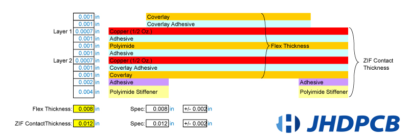
PI stiffeners serve as a cost-effective alternative to FR4. They are frequently employed to increase the thickness of the ZIF connector, ensuring proper contact and support. This allows for tolerance stackup in bending thickness and contours the component at the contact point.
In addition, PI stiffeners are utilized to limit the bending capability of certain areas on the PCB, ensuring they are well-prepared for final assembly. When wear becomes a concern, hole locations are reinforced with PI stiffeners to enhance wear resistance.
These stiffeners exhibit outstanding solder resistance and possess strong bond strength. They are typically applied to the backside of the insertion gold fingers, facilitating the insertion of flexible printed circuit connector fingers into ZIF sockets or connectors.
⑵ FR4 Stiffener:
FR4 is commonly used as the CCL (Copper Clad Laminate) for rigid printed circuit boards and is a popular material for PCB stiffener applications in flex circuits. The primary purposes of using FR4 stiffeners are:
➨ Providing sufficient support during pick-and-place and reflow processes for flexible PCBs to maintain flatness.
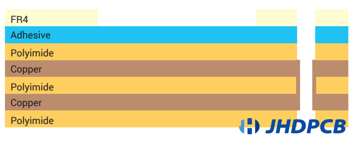
➨ By positioning the stiffeners on the same side of the flex PCB where the components are inserted, direct access to solder pads for plated-through hole (PTH) components is facilitated. In some cases, an FR4 frame can be added to the border of a panelized PCB to replace the more expensive SMT carrier, resulting in cost savings during the project assembly. The below image is one of the example of 2 layer pcb stackup or layer buildup with FR4 PCB stiffener.
⑶ Stainless Steel/Aluminum Stiffener:
Stainless steel or aluminum stiffeners are utilized in flexible circuit designs that necessitate attributes such as anti-corrosion resistance, robustness, formability, and capability. These stiffeners are usually added to the connecting fingers of flexible printed boards to strengthen them and facilitate assembly.
⑷ Using MultiLayer PCBs Stiffeners
When applying PCB stiffeners, manufacturers ensure that the stiffener overlaps the bored overlay by 0.030″ to alleviate stress. The overlay acts as a solder resistor for the flexible printed circuit board in this scenario.
Furthermore, it is also important if you maintain the same thickness for multiple stiffeners. Once the process is completed, the stiffeners enhance the strength of the solder joints by providing increased abrasion resistance.
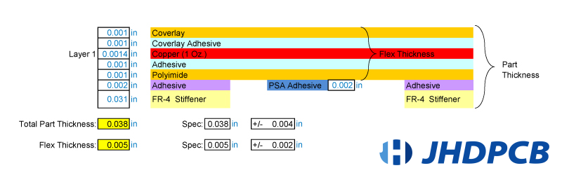
1 Layer Flex PCB with Optional FR-4 Stiffeners and PSA
2 Layer Flex Circuit with ZIF Contact Fingers
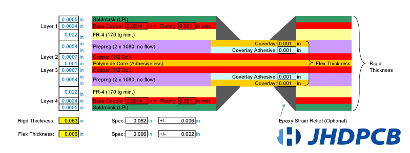
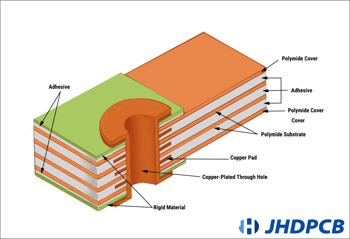
4 Layer Rigid-Flex PCB (2 Flex Layers)