
Lead or Lead-Free Solders?
The first decision you need to make when choosing a PCB solder is whether to use a lead-based or lead-free solder. Each type has its advantages and disadvantages, which should be carefully weighed before making a decision.
Lead-based solders contain 60-40 or 63/37 tin/lead and have been used traditionally due to their low cost and low melting point. However, lead is toxic, so lead-free solders like SAC305 (Sn96.5Ag3Cu0.5) are now more common to comply with regulations. Lead-free solders have higher melting points so require higher temperatures, but are more environmentally friendly. The choice depends on your priorities and application needs.
Chemical Contents of Solder
Here, you can narrow your search for different types of solder flux for electronics into three primary categories.
- Flux Core Solder:
Flux core solder is a type of solder that contains a central core of flux, which is a chemical agent that aids in the soldering process by reducing oxidation and improving the flow of the solder. Flux core solder is available in both lead-based and lead-free varieties and is commonly used in electronics assembly due to its ease of use and reduced need for additional flux application. - Lead Solders:
Traditional lead-based solders are typically composed of a tin-lead alloy, with the most common being a 63/37 (63% tin, 37% lead) composition, also known as eutectic solder. This solder has a low melting point (183°C) and excellent wetting properties, making it easy to work with and reliable in electronic applications. - Lead-Free Solders:
Lead-free solders come in various alloy compositions, with the most common being tin-silver-copper (SAC) alloys. Other alternatives include tin copper, tin-bismuth, and tin-zinc alloys. Each alloy has different properties, such as melting points and wetting characteristics, so it’s essential to choose the appropriate lead-free solder for your specific application.
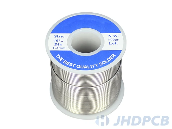
Solder Diameter
The diameter of the solder wire can significantly impact the soldering process. Thicker solder wires can provide more material per length, making them suitable for large joints or high-volume applications. In contrast, thinner solder wires offer better control and precision, making them ideal for intricate soldering tasks, such as surface mount components on PCBs. It’s crucial to select the appropriate solder diameter based on your project’s specific requirements.
Shelf Life of Solder
The shelf life of Flux-cored solder wire is determined by the alloy used in the solder. Alloys containing more than 70% lead have a shelf life of 2 years, while other alloys have a shelf life of 3 years.
If you are looking for a solder with a longer shelf life, lead-free solders are a good option. They typically have a longer shelf life than lead-based solders, making them ideal if you do not plan on using the entire solder reel at once.
Wire Size
The size of the solder wire spool will depend on the volume of soldering work you anticipate for your project. For small projects or occasional soldering tasks, a smaller spool may suffice. However, for high-volume production or regular soldering work, a larger spool may be more cost-effective and convenient in the long run.
For instance, For PDIPs with 0.1-inch pin spacing, a gauge of 18 (1.22mm) is recommended. For smaller PCBs with pins that are closer together, a 22-gauge wire numbered with a diameter of 0.711 mm is suitable. On the other hand, older circuits with solder larger tags require a thicker wire gauge, such as 16-gauge wires with a diameter of 1.63mm. It’s important to select the right wire gauge to ensure proper connectivity, durability, and compatibility with the specific circuit board being used.
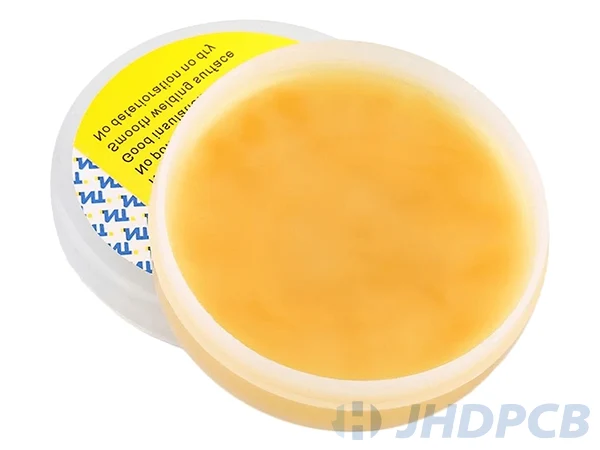
Flux Form
Flux is an essential component in the soldering techniques as it helps to clean the area to be soldered, allowing the solder to flow and create a perfect solder joint. Flux works by changing the surface tension of the materials being soldered, which increases the adhesion properties of the solder joint.
There are two main types of flux available: water-soluble, and rosin core solder for electronics.
- Water-soluble flux is a good option for circuits because it simplifies the cleaning process and can help minimize the amount of solder inventory needed.
- Rosin core flux wire is typically enough for most soldering applications, but it can be helpful to have separate flux on hand to add to the soldering point’s surface. This can be done by leaving the flux on top of the soldering iron and then applying it to the joint as needed.
Cost of Solders
The cost of solder can vary significantly depending on factors such as the alloy composition, the diameter of the solder wire, and the size of the spool. Lead-based solders are generally less expensive than lead free solders. However, it is possible to achieve desired solder properties by incorporating other metals such as silver and bismuth. Silver-coated solders are more expensive than tin-based solders, but they offer greater strength. Bismuth-based solders are also costly due to their ability to operate at low temperatures. When comparing the costs of different solders, it’s essential to consider not only the upfront costs but also the long-term costs associated with factors such as solder performance, reliability, and compliance with environmental regulations.
Solder Based on Your Project
For Beginners:
For hobbyists or those new to soldering, a lead-free solder with a low melting point and good wetting properties is recommended. This will provide a more forgiving soldering experience and minimize the risk of damaging components or the PCB.
When to Choose Lead-Free Solder?
For professional applications and projects subject to RoHS regulations, lead-free solder is required. The lead free solder with appropriate alloy composition, such as SAC, to ensure optimal performance and compliance with environmental regulations.
When to Choose Lead-Based Solder?
In some cases, lead-based solder may still be the preferred choice, particularly for applications where RoHS compliance is not required, and the superior wetting properties and a lower melting point of lead-based solder can provide better performance and ease of use.
Consider the Nature of Your Electronic Product
Lastly, the nature of your electronic product should be taken into account when choosing PCB solder. Evaluate the product’s intended use, longevity, operating conditions, and any specific requirements for reliability, performance, or compliance with industry standards. These factors can help guide your decision on the appropriate solder circuit board type and composition for your project.
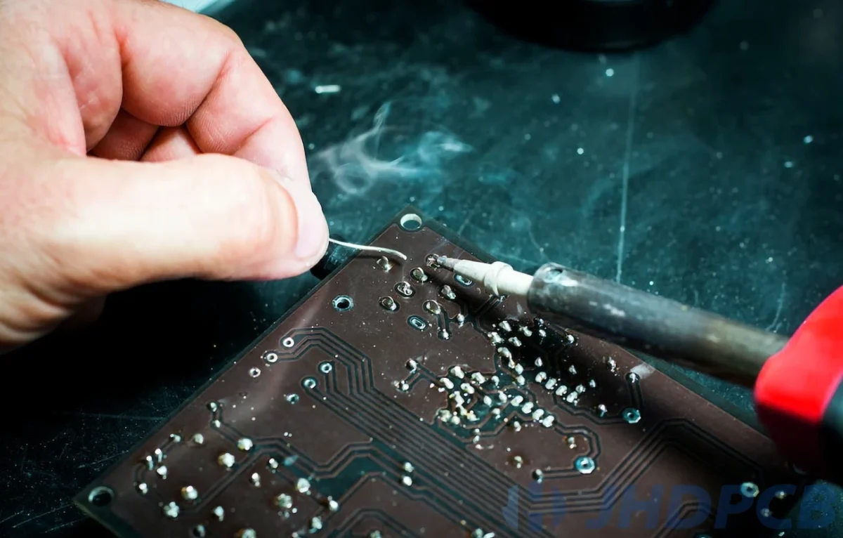
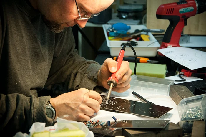
- Step 1: Tin the Solder Iron.
The first step in soldering is to prepare your soldering iron by tinning its tip. Tinning helps improve heat transfer, protects the iron from oxidation, and makes it easier to solder components to the PCB.
Plug in the soldering iron and allow it to heat up to its operating temperature. This may take a few minutes depending on the iron’s wattage. Clean the tip of the iron using a wet sponge or brass wire sponge. This removes any debris or oxidation that might have formed on the surface.
Apply a small amount of solder to the tip of the soldering iron. Once the solder melts it will coat the tip. This is called tinning. Wipe away any excess flux or solder using the sponge or brass wire sponge, leaving a thin layer of solder on the tip. - Step 2: Prepare the Surface.
Before you begin soldering, it’s important to prepare the PCB and the components you’ll be soldering onto it. Clean the PCB using a lint-free cloth to remove any dust, grease, or fingerprints that might be present. Insert the components through the appropriate holes in the PCB. Bend the leads to keep the components in place temporarily. Secure the PCB using a PCB holder or a helping hand tool to keep it steady while you work. - Step 3: Component Placement.
Double-check the orientation of each component on the PCB according to the schematic or layout diagram. Ensure that polarized components, such as diodes and capacitors, are correctly oriented. Align the components so that they sit flush against the PCB, making sure there are no gaps between the component body and the surface of the board. - Step 4: Heat the Joint.
Hold the soldering iron in one hand and the solder in the other. Touch the tip of the soldering iron to both the component lead and the corresponding PCB pad. Hold it steady for a few seconds to allow the heat to transfer and heat up both surfaces. - Step 5: Solder the Joint.
Apply a small amount of solder to the heated joint by touching the solder to the junction of the component lead and PCB pad. The solder should melt and flow evenly around the joint, creating a shiny, concave filet. Remove the solder from the joint, but continue to hold the soldering iron in place for a couple more seconds. This ensures that the solder has fully flowed and created a strong bond. Gently remove the soldering iron from the joint, allowing the solder to cool and solidify. - Step 6: Inspect the Joint.
Inspect the solder joint using a magnifying glass or microscope to ensure that it has formed a smooth, shiny, concave filet with no cracks or gaps. A good solder joint should completely cover the pad and show a clear connection between the component lead and the PCB.
Trim the excess component leads using flush cutters, leaving a small amount of tin lead protruding beyond the solder joint. - Step 7: Cleanup.
Clean up the PCB using isopropyl alcohol and a lint-free cloth to remove any flux residue that might remain after soldering. Flux residue can cause corrosion and affect the performance of the circuit over time. Unplug the soldering iron and allow it to cool before storing it safely.
By following this step-by-step guide, you can ensure that you’ll be able to solder components onto a PCB with confidence and precision. With practice, you’ll become more proficient in soldering and be well-equipped to tackle a variety of electronics projects.
Up until this point, we have focused on how to properly solder components onto circuit boards and join wires. However, it is important to also know how to safely remove soldered components when needed. This process is known as desoldering.
At some point, you may need to remove an electronic component that you previously soldered onto a circuit board. Perhaps you soldered the wrong component initially or sourced a replacement part to improve your circuit. In these situations, a desoldering tool will allow you to safely remove the component and its solder.
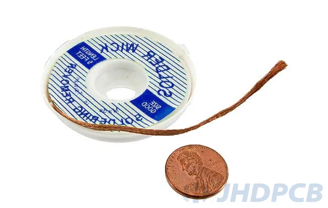
Steps:
- Place the desoldering wick over the solder joint to be removed. Then, press the heated soldering iron tip onto the desoldering wick. The solder will be absorbed into the wick. Click to learn more about solder wicks.
- Remove the desoldering wick after it has absorbed all the solder.
- Cut off the used section of the wick using wire cutters.
- Repeat the above steps if some solder remains. The absorbability may vary depending on the type of solder. Solders with 63% and 60% tin content have good absorbability.