Applying the IPC 2221 standard to printed circuit board design.

jhdpcb@gmail.com
As technology advances, so does the complexity of PCB design. It is essential to adhere to industry standards in order to produce reliable and safe PCBs. One of the most important standards in PCB design is the IPC-2221 standard.
IPC-2221 specifies general standards for PCB design, component mounting and interconnection.
What is ipc-2221 standard?
IPC-2221 is a standard published by the Association of Connecting Electronics Industries (IPC) that provides guidelines for designing printed circuit boards (PCBs). The standard is widely recognized in the electronics industry and is often used as a reference by engineers and PCB designers.
IPC 2221 voltage spacing covers various aspects of PCB design, including board thickness, layer count, trace width and spacing, hole size, placement, creepage clearance, voltage clearance, insulation requirements and solder mask requirements. The standard also includes guidelines for designing boards that are compatible with automated assembly equipment, as well as recommendations for testing and inspecting finished boards.
What functions does IPC-2221 do?
IPC-2221 covers various aspects of PCB design. The standard also includes guidelines for designing boards that are compatible with automated assembly equipment, as well as recommendations for testing and inspecting finished boards.
Standards compliant:
One of the key benefits of using IPC-2221 is that it helps ensure that PCBs are designed to meet industry standards for reliability and performance. By following the guidelines set forth in the standard, designers can help reduce the risk of errors and defects that can lead to costly rework or even product failure.
Easy to Communicate:
Another advantage of using IPC-2221 is that it provides a common language and framework for communication between designers, manufacturers, and other stakeholders in the PCB supply chain. This can help streamline the design and production process, as well as facilitate collaboration and knowledge sharing.
The function of IPC-2221.
- For specific applications:
The first function of IPC-2221 is to provide guidelines for PCB design for specific applications. The standard is divided into different ipc classes for pcb, each with specific requirements for the PCB design. For example, IPC-2221 class 3 is the most stringent requirement for PCB design, and is often used in aerospace, military and medical applications. By following the guidelines, designers can ensure that their PCB design meets the requirements for their intended application. - For appropriate widths:
Another key function of IPC-2221 is to provide guidelines for determining trace width, IPC-2221 clearance calculator, and IPC-2221 current carrying capacity. These guidelines are essential for determining the appropriate widths for PCB traces, the spacing between traces, and the amount of current that can flow through a particular trace. By adhering to these guidelines, designers can prevent problems such as signal interference and overheating, which can lead to PCB failure. - For spacing and voltage requirements:
IPC-2221 also provides guidelines for determining the appropriate PCB spacing and voltage requirements. This helps to ensure that the PCB design is safe and reliable, and prevents damage from high voltage or current carrying capacity. The ipc 2221 generic standard on printed board design covers a range of aspects in PCB design, including board design, generic standards, printed circuits and more. Click to read detailed PCB trace spacing guidance. - Component Placement:
IPC 2221 offers recommendations for the placement of IC components on a PCB. This includes guidance on the spacing between components, the orientation of components, and the overall layout of the board. - Thermal Considerations:
IPC 2221 provides guidance on how to manage the thermal performance of a PCB. This includes recommendations for the use of heat sinks, the placement of components to minimize heat buildup, and the use of thermal vias to dissipate heat. - Materials Selection:
IPC 2221 offers guidance on the selection of materials for a PCB, including recommendations for the use of specific materials in different applications. This includes guidance on the use of copper, dielectric materials, and solder mask materials. - Manufacturing Processes:
IPC 2221 provides guidance on the manufacturing processes used to fabricate a PCB, including recommendations for the use of specific processes for different types of applications. This includes guidance on the use of surface mount technology (SMT), through-hole technology (THT), and the use of specific manufacturing techniques for high-reliability applications.
What clearance standards does IPC-2221 define for production?
Common clearance table.
IPC-2221 provides a common clearance table that specifies the minimum clearance distances required for various voltage levels and environments. These clearance distances are important to ensure that there is no arcing or electrical breakdown between different conductive elements on the PCB. The common clearance table in IPC-2221 creepage and clearance, includes minimum distances for air gaps, creepage, and clearance between conductors on the same layer and adjacent layers. Gap distance is the distance measured in air between two conductors or solder joints.
Creepage is the distance between two conductive elements along the surface of the PCB. It is an important factor in determining the electrical safety of a PCB, especially in high voltage applications. IPC-2221 defines the creepage requirements for different voltage levels and environments in the common clearance table. The creepage distance required depends on factors such as the voltage level, pollution degree, and material used for the PCB.
| Optimum clearance required for specific features | |
|---|---|
| Feature | Clearance |
| Test probe sites | 80% of the component height (0.6 mm minimum and 5 mm maximum) |
| Component leads | 0.13 mm (up to a voltage of 50V) |
| Uncoated conducting areas | 0.75 mm |
| PTH relief in the heat sink | 2.5 mm larger than the hole (includes electrical clearance and misregistration tolerance) |
| Mounting hardware | Should not protrude more than 6.4 mm below PCB surface |
| IPC-2221 mask clearance and dams values for solder masks | ||
|---|---|---|
| Mask type | Clearance | Dam |
| LPI | 0.051 mm | 0.1 mm |
| Liquid screenable | 0.25 mm | 0.25 mm |
| Photoimageable dry film ≤0.0635mm | 0.051 mm | 0.127 mm |
| Photoimageable dry film 0.066 to 0.1mm | 0.051 mm | 0.25 mm |
PCB Track Thickness.
Printed IPC circuit boards (PCBs) are the backbone of modern electronics, and they consist of a layer of copper traces on a substrate material. The thickness of the copper traces on a PCB plays a critical role in determining the reliability and performance of the IPC board.
The thickness of a PCB ipc 2221 trace width is measured in ounces (oz) and represents the weight of copper per square foot of the board. For example, a 1 oz PCB has a thickness of 1.4 mils (0.0356 mm), while a 2 oz PCB has a thickness of 2.8 mils (0.0711 mm).
The appropriate thickness of PCB traces depends on various factors, including the current capacity, the voltage drop, and the required impedance. You can click to view more detailed PCB traces guide.
IPC-2221 also provides guidelines for determining the trace width and height of the conductive elements on a PCB. The trace width and height are important factors in determining the current carrying capacity and resistance of the conductive elements. IPC-2221 trace width formula provides a formula for calculating the required trace width based on factors such as the current carrying capacity, ambient temperature, and copper weight. The formula is designed to ensure that the trace can carry the required current without overheating or excessive voltage drop.
- Width [mil]=Area [mil²] / (Thickness [oz] x 1.378 [mil/oz])
In summary, IPC-2221 defines important clearance standards for PCB production, including the common clearance table for minimum clearance distances, creepage requirements for different voltage levels and environments, and guidelines for determining trace width and height. By following these guidelines, PCB designers and manufacturers can ensure that their products are safe and reliable for their intended applications.
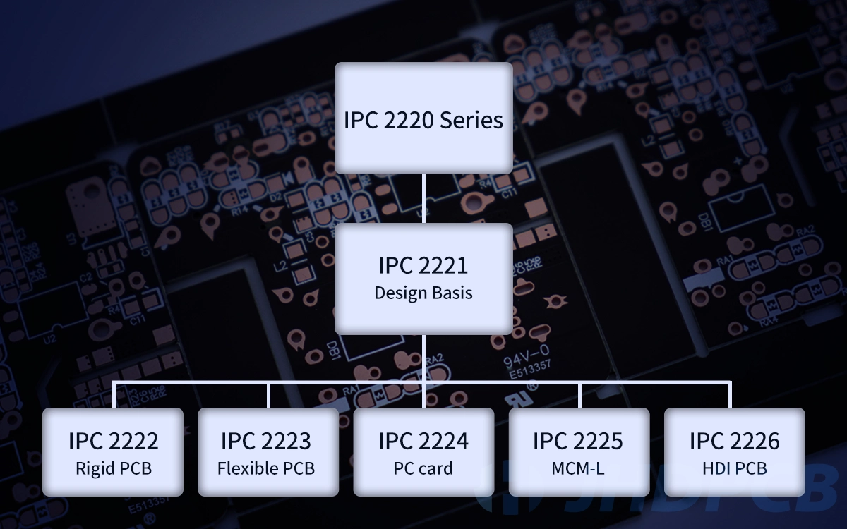
IPC-2221 series documents and their application.
The IPC-2221 standard and IPC-2222, IPC-2223, IPC-2224, IPC-2225 and IPC-2226 belong to the IPC-2220 series. These documents provide guidelines and requirements for printed circuit board (PCB) design. Below, we summarize the structure of each document, their application, and the relationships among them.
- IPC-2220: Generic Standard on Printed Board Design.
IPC-2220 is a generic standard that provides guidance on the design of PCBs. The document covers all aspects of PCB design, including the design process, component selection, layout, and fabrication. IPC-2220 is used by PCB designers, manufacturers, and assemblers to ensure that the PCBs meet the required specifications and are reliable. - IPC-2221: Guidelines for PCB Design.
IPC-2221 is a document that provides guidelines and requirements for PCB design. IPC-2221 is relatively broad, covering design considerations for single-sided, double-sided, and multilayer PCBs, as well as flex and rigid-flex PCBs, and high-speed and high-frequency PCBs. - IPC-2222: Sectional Design Standard for Rigid Organic Printed Boards.
IPC-2222 is a document that provides guidelines for the design of rigid organic printed boards. The document covers the design considerations for single-sided, double-sided, and multilayer boards, as well as high-density interconnect (HDI) boards. IPC-2222 is used by PCB designers, manufacturers, and assemblers to ensure that the rigid organic printed boards meet the required specifications and are reliable. - IPC-2223: Sectional Design Standard for Flexible Printed Boards.
IPC-2223 is a document that provides guidelines for the design of flexible printed boards. The document covers the design considerations for single-sided, double-sided, and multilayer boards, as well as rigid-flex boards. IPC-2223 is used by PCB designers, manufacturers, and assemblers to ensure that the flexible printed boards meet the required specifications and are reliable. - IPC-2224: Sectional Design Standard for Organic Multichip Modules (MCM-L)
IPC-2224 is a document that provides guidelines for the design of organic multichip modules (MCM-L). The document covers the design considerations for MCM-Ls, including the design process, layout, fabrication, and assembly. IPC-2224 is used by PCB designers, manufacturers, and assemblers to ensure that the MCM-Ls meet the required specifications and are reliable. - IPC-2225: Sectional Design Standard for Organic Land Grid Array (LGA)
IPC-2225 is a document that provides guidelines for the design of organic land grid array (LGA) packages. The document covers the design considerations for LGAs, including the design process, layout, fabrication, and assembly. IPC-2225 is used by PCB designers, manufacturers, and assemblers to ensure that the LGAs meet the required specifications and are reliable. - IPC-2226: Sectional Design Standard for High Density Interconnect (HDI) Boards.
IPC-2226 is a document that provides guidelines for the design of high density interconnect (HDI) boards. The document covers the design considerations for HDI boards, including the design process, layout, fabrication, and assembly. IPC-2226 is used by PCB designers, manufacturers, and assemblers to ensure that the HDI boards meet the required specifications and are reliable.
IPC-2221 standard and IPC-2222, IPC-2223, IPC-2224, IPC-2225, IPC-2226 documents are interrelated and complementary. You can choose the appropriate IPC design standard document according to the actual application scenario.
How to choose materials according to IPC 2221 standard?
Choosing the right materials is an important aspect of designing printed circuit boards (PCBs). The IPC 2221 standard provides guidelines for choosing PCB materials based on their characteristics and properties.
When choosing materials for PCB design, it is important to consider the following characteristics:
- Dielectric constant: The dielectric constant is a measure of a material’s ability to store electrical energy in an electric field. A low dielectric constant is desirable for high-frequency applications, while a higher dielectric constant may be needed for lower frequency applications.
- Thermal conductivity: The thermal conductivity of a material determines how well it can dissipate heat. Materials with high thermal conductivity are preferred for applications that generate a lot of heat.
- Tensile strength: Tensile strength is the maximum stress that a material can withstand without breaking. High tensile strength is important for applications that require mechanical stability and durability.
- Coefficient of thermal expansion (CTE): The CTE of a material determines how much it will expand or contract as temperature changes. A low CTE is desirable to minimize mechanical stress on the PCB.
- Moisture absorption: Moisture absorption can cause changes in the dielectric constant and other properties of the material. Low moisture absorption is preferred to ensure stability of the PCB.
- Commonly recommended materials: Based on the above characteristics, the IPC 2221 standard recommends the following materials for different applications:
FR-4: FR-4 is a widely used and versatile material for PCBs. It has a low cost, good electrical properties, and good mechanical strength. It is suitable for many applications, including high-frequency circuits.
Polyimide: Polyimide is a high-temperature material that can withstand high temperatures and has good electrical properties. It is commonly used in applications that require high reliability and stability.
PTFE: PTFE is a low-loss material with excellent electrical properties and a high-temperature rating. It is commonly used in high-frequency and microwave applications.
Ceramic: Ceramic materials have high thermal conductivity and can dissipate heat well. They are commonly used in applications that generate a lot of heat, such as power electronics. - Organic Protective Coatings: Some common types of organic protective coatings include acrylics, epoxies, and polyurethanes. Acrylics are a popular choice for PCBs because they provide good electrical insulation and are resistant to moisture and chemicals. Epoxies are also widely used as they provide excellent mechanical protection and are resistant to high temperatures. Polyurethanes offer a high level of flexibility, making them ideal for use in applications where the board may be subjected to vibration or movement.
- Semiconductive Coatings: The thickness of the semiconductive coating is critical as it determines the level of conductivity. If the coating is too thick, it can affect the electrical properties of the board, leading to reduced performance. If it is too thin, it may not provide adequate ESD protection.
In summary, when choosing materials for PCB design, it is important to consider material characteristics such as dielectric constant, thermal conductivity, tensile strength, CTE, and moisture absorption. By choosing the right materials, designers and manufacturers can create PCBs that meet the electrical, mechanical, and thermal requirements of their intended applications.
What are IPC-2221 recommendations for insulation resistance?
Insulation resistance is an important consideration in the design and manufacturing of printed circuit boards (PCBs). It is a measure of the ability of the PCB’s insulation to prevent current leakage between different conductive elements, and is critical to ensuring the safe and reliable operation of electronic devices.
The IPC-2221 standard provides guidelines for the minimum insulation resistance required for PCBs, based on the operating voltage and environmental conditions of the application. The standard divides applications into different IPC PCB classes, based on factors such as operating voltage, pollution degree, and ambient temperature. Each class has a different minimum insulation resistance requirement. For example, for Class 1 and IPC 600 Class 2 applications (low voltage, clean environments), the minimum insulation resistance requirement is 1 megohm at room temperature and 500 kilohms at elevated temperatures. For IPC Class 3 applications (high voltage, harsh environments), the minimum insulation resistance requirement is 100 megohms at room temperature and 50 megohms at elevated temperatures.
To ensure that a PCB meets the required insulation resistance, designers and manufacturers can take a number of steps. These include:
- Choosing materials with high dielectric strength and low moisture absorption, which can help to minimize current leakage and increase insulation resistance.
- Ensuring that the spacing between conductive elements on the PCB meets the minimum clearance requirements specified by IPC-2221, which can help to prevent arcing and improve insulation resistance.
- Using conformal coatings or other protective measures to protect the PCB from environmental factors that can degrade insulation resistance, such as humidity, moisture, and contamination.
- Performing insulation resistance testing during the manufacturing process to verify that the PCB meets the minimum requirements specified by IPC-2221.
IPC-2221 provides recommendations for minimum insulation resistance for PCBs, based on the operating voltage and environmental conditions of the application. To ensure that a PCB meets these requirements, designers and manufacturers can choose materials with high dielectric strength and low moisture absorption, follow minimum clearance requirements, use protective measures, and perform insulation resistance testing during manufacturing. By following these guidelines, designers and manufacturers can create PCBs that are safe, reliable, and meet the needs of their intended applications.
How should the IPC-2221 standard be adjusted in the case of high voltage circuits?
The ipc-2221 voltage and spacing standards provide guidelines for the design of printed circuit boards (PCBs), including the minimum clearances required between conductive elements on the board to ensure safe and reliable operation. However, in the case of high-voltage circuits, additional considerations may need to be taken into account to ensure that the PCB can handle the high voltage levels without experiencing electrical breakdown or arcing.
- One of the key factors to consider when designing a PCB for high-voltage applications is the minimum clearance distance between conductive elements. The IPC-2221 standard provides a table of minimum clearance distances based on the operating voltage and environmental conditions of the application. However, in the case of high-voltage circuits, it may be necessary to increase the clearance distances to prevent arcing or electrical breakdown.
- In general, the minimum clearance distance should be increased in proportion to the operating voltage of the circuit. For example, if the standard calls for a minimum clearance of 0.4 mm for a circuit operating at 300 volts, the clearance distance should be increased to 1 mm or more for a circuit operating at 1000 volts or more.
- Another factor to consider in high voltage circuits is the selection of materials. Materials with high dielectric strength and low moisture absorption should be used to minimize current leakage and increase insulation resistance. It is also important to ensure that the materials used are compatible with the environmental conditions of the application, such as temperature and humidity.
- In addition to these considerations, it may be necessary to perform additional testing and validation to ensure that the PCB can handle the high voltage levels. This may include testing for insulation resistance, high voltage breakdown, and other factors.
In summary, when designing a PCB for high voltage circuits, the IPC-2221 standard should be adjusted to increase the minimum clearance distances and select appropriate materials. Additional testing and validation may also be necessary to ensure the safety and reliability of the PCB. By following these guidelines, designers and manufacturers can create high voltage PCBs that meet the needs of their intended applications and ensure safe and reliable operation.
What is the difference between IPC-2581 and IPC-2221?
IPC-2581 and IPC-2221 are two important standards in the electronics industry, and understanding their differences is crucial for anyone involved in PCB (Printed Circuit Board) design and manufacturing.
- IPC-2221: IPC-2221 is a generic standard for designing PCBs. Ipc 2221 rule provides guidelines and rules for the design of PCBs, including the mechanical, electrical, and thermal aspects. This standard covers the design of the PCB itself, including the layout, component placement, and trace routing. It also includes guidelines for the choice of materials, via sizes, and board thicknesses. IPC-2221 is a widely accepted standard in the PCB industry and is used by many designers and manufacturers as a reference for their PCB designs.
- IPC-2581: IPC-2581 is a specific standard for the exchange of PCB design data between different software tools and systems. This standard defines a unified data format that can be used to transfer PCB design information between different software applications and manufacturing systems. This allows for the seamless transfer of design data from one system to another, which is essential for efficient and accurate PCB manufacturing. IPC-2581 includes information about the PCB design itself, such as layer stackup, drill sizes, and trace routing, as well as information about manufacturing processes and test requirements.
One of the key benefits of using IPC-2581 is that it eliminates the need for multiple data formats and file conversions, which can introduce errors and inconsistencies in the design data. With IPC-2581, all design and manufacturing data is stored in a single, standardized format, which reduces the risk of errors and makes the data more accessible and usable by different systems.
In summary, IPC-2221 is a standard for the design of PCBs, while IPC-2581 is a standard for the exchange of PCB design data. While IPC-2221 provides guidelines for the design of the PCB itself, IPC-2581 provides a standardized data format for the transfer of design and manufacturing information between different software tools and systems. Both standards are important in the PCB industry and should be considered by anyone involved in PCB design and manufacturing.
By understanding the differences between IPC-2221 and IPC-2581, designers and manufacturers can ensure that their PCB designs are accurate, consistent, and efficient. Whether you are designing a new PCB or working with existing designs, it is important to stay up-to-date with the latest standards and best practices in the industry to ensure that your products are of the highest quality.
In conclusion, the IPC standards for pcb play a critical role in ensuring the performance and reliability of Printed Circuit Boards (PCBs) during the design and manufacturing process. IPC-2221 is a widely used standard that defines guidelines for the design of PCBs. It also provides recommendations for selecting appropriate materials for PCB design.
It is important for anyone involved in PCB design and manufacturing to stay up-to-date with the latest standards and best practices in the industry. This includes understanding the clearance requirements defined by IPC-2221 and other relevant standards, and ensuring that all pcb design standards meet these requirements. By doing so, designers and manufacturers can create high-quality, reliable PCBs that meet the needs of their customers and end-users. If you still have doubts about your PCB design, you can send us the relevant files. We will conduct free DFM inspections to meet subsequent manufacturing work and reduce unnecessary losses.