Through hole assembly
directory
what is through-hole assembly(THA)?
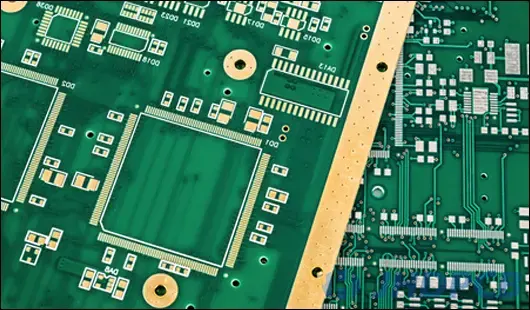
Through-hole technology has a lasting effect with its reliability and strength, and still win a large market advantage. THA-Through hole assembly is difficult to meet the demands of modern electronic products. Nowadays, SMT technology has almost replaced the through-hole design in PCB manufacturing. But through-hole assembly still impossible to replace in some applications, such as large transformers, electrolytic capacitors, connectors, etc.
Thru hole PCB assembly service.
Through hole (or through hole) technology involves drilling holes in a printed circuit board that can connect leads. Comparing with surface mount through hole PCB assembly service is an older technology.
Although this is an older process, automated through-hole assembly also has some benefits. Through hole installation technology establishes a stronger combination between the circuit board and its components, so that the product is more durable, more resistant to impact and impact.
What is a through-hole component(THC)?
THC-Through-hole components (also known as “through-hole”) are a mounting solution for electronic circuits in which components are fixed by wire. A mounting process in which wires are plugged into holes on a printed circuit board (PCB) and components are soldered to the PCB board by wave soldering or hand soldering.
The quality of is important for many reasons. Solder joints are the actual connections between the component and the circuit board. The quality of the soldering joint is equal to the quality of the connection. The “look” of a solder joint is usually ugly, but it usually indicates the quality of the solder joint.
What are the features of through-hole components?
·High reliability
Through hole components provide higher environmental adaptability, because the components are fixed on the board through the lead wire inserted in the hole, rather than simply welded to the PCB surface like SMT components. Therefore, through-hole assembly supplies a stronger physical connecting, making it the process of choice for the military and aerospace industries with high-reliability requirements.
·Easy to operate manually
Through-hole components are easier to move or replace their location, making this assembly way widely used in applications which need PCB prototyping and PCB testing.
·Higher durability
Through-hole components are often found in the LED lights on the large advertising board due to their high heat resistance and high adaptability.
·Low manufacturing efficiency
Due to the additional steps of drilling and fixing components with leads, through-hole assembly is very time-consuming, resulting in high costs.
·Limited PCB design
Through-hole assembly is not fit for multi-layer PCBs because the drilled holes must cover all layers of the PCB board, which increases the difficulties of layout designing and PCB fabrication. In addition, the size of the entire circuit board will be larger than that of the SMT PCB, thus causing more restrictions on its application field.
Jhdpcb provides semi-automatic, fully automatic and manual insertion technology for through-hole assembly. If you need more through-hole technical information related to PCB projects, please contact us.
How to Solder thru-hole component?
Below four figures show the general steps for welding through-hole components.
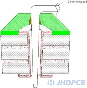
In step 1, Holes and pads to be welded.
Prepare the hole and pad to be welded and put the lead into/through the hole. The lead wires shall be placed in such a way that the bending is maintained above the welding area, thereby reducing heat and welding requirements.
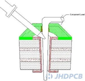
In step 2, Evenly heat leads and pads/holes.
Evenly heat the lead and pad/hole to heat the material so that the solder adheres to the two surfaces.
In step 3, Touch the end of the iron.
The solder contacts the end of the soldering iron, causing the solder to become liquid and then flow into the hole.
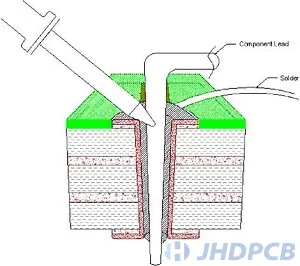
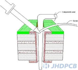
In step 4, Welding leads.
Solder flows through the holes, creating mounds on the top and bottom. Since the lead is soldered from the top, check the bottom for adequate solder and joint quality. Some components may need to be welded from both sides to ensure quality. There is enough clearance in the holes to allow good solder flow through the board, and the solder is only allowed on one side. Tight gaps may require soldering on both sides, increasing automated through hole soldering time. through hole assembly inspection also be important.
The two main types and List of through hole components.
There are two automated assembly methods for through-hole – axial components and radial lead components. Axial leads run in a straight line (axial) through the component, with each end of the lead connecting to either end of the component. Radial lead assemblies, on the other hand, stick out of the board because their leads are on one side of the assembly.
Common through-hole integrated circuit packaging processes are:
- SIP: Single In-Line Package;
- ZIP: Zigzag In-line Package;
- DIP: Dual in-line package;
- PGA: Pin Grid Array;
1. Axial Lead Assemblies:
As previously mentioned, axial leads extend from both ends of a typically cylindrical or elongated box-shaped member on an axis of geometric symmetry. Axial lead elements are shaped like jumper wires and can be used to span short distances on a PCB (printed circuit board), or even make unsupported connections through open spaces in point-to-point wiring. Axial components do not protrude much from the PCB surface, creating a low profile or flat configuration when placed parallel to the PCB board. In this regard, axial lead assemblies allow designers to easily create devices that fit in tight spaces.
| Axial Lead Assemblies | ||
|---|---|---|
| Diode | Resistor | Capacitor (axial lead) |
| Carbon Film Resistors | Rectifier diode | Inductor |
2. Radial Lead Assemblies:
Radial leads are outlined roughly parallel from the same surface or side of the component container, not from both ends of the package. Originally, Radial leads are clarified according to the radius of a cylindrical segment in varying degrees. Over time, this definition has been promoted and taken on in its popular form compared to axial leads. When placing on a circuit board, radial components are placed vertically and take up less space than their counterparts, making them useful in many high-density projects. Parallel wires extending from a single mounting surface provide the flexibility and mobility of radial components for use in high-speed automatic component insertion machines in manufacturing, including:
| Radial Lead Assemblies | |||
|---|---|---|---|
| Capacitor | Translator | Ceramic capacitors | Coaxial connector |
| Electrolytic capacitors | Connector | Potentiometer | Transistor |
| Voltage Regulator | Relay | Voltage converter | Varistor or Voltage Dependent Resistor (VDR) |
| Recovery Fuse | MOSFET | LED | RGB |
| Photodiode | Integrated circuit | Laser rangefinder | Photoresist |
| Switch | Button | Semiconductor | |
Through-Hole vs Surface Mount
In recent years, with the increasing demand for larger functions, smaller sizes and increased practicality, semiconductor packaging has developed. In current PCBA design, there are two main ways to install components on PCB: through-hole installation and surface installation.
Through hole mounting (THM):
Through hole installation is the process of placing the component lead in the drill hole on the bare PCB board.The through hole assembly process was standard practice until surface mount technology (SMT) rise abruptly in the 1980s, when through-holes were expected to be phased out entirely.However, despite the sharp decline in popularity over the years, through-hole technology has proved resilient in the SMT era, providing many advantages and niche applications: reliability.
Through-hole components are most suit for high-reliability products which require stronger connecting between layers. SMT components are only fixed by solder on the surface of the circuit board, while through-hole component leads pass through the circuit board, so that the components can withstand more environmental stress.That’s the reason hole technology is usually used in military and aerospace products that may undergo extreme accelerations, impacts, or high temperatures. Through-hole technology is also useful in test and prototyping applications where manual adjustments and replacements are sometimes required.In general, the complete disappearance of through holes from PCB assembly is a widespread misunderstanding. In addition to the above-mentioned uses of hole technology, availability and cost factors should always be kept in mind. Not all components are able to be used as SMD packing, and part of through-hole components with lower cost.
Surface Mount Technology (SMT):
SMT is the process of mounting components directly on the surface of PCB board. This method, originally known as “plane installation”, was developed in the 1960s and has become more and more popular since the 1980s. Nowadays, almost all electronic hardware is made by SMT. It has become a necessary condition for PCB design and manufacturing, which improves the overall quality and performance of PCB, and greatly reduces the processing and processing costs. Click to view detailed surface mount technology knowledge.
The main differences between SMT and through-hole mounting process are:
- SMT does not require drilling holes on the PCB;
- SMT components are much smaller;
- SMT components can be mounted on both sides of the PCB surface.The ability to install a large number of small components on the board allows for denser, higher performance, and smaller PCBs.
Through-hole component leads that go through the board and connect all layers of the board have been replaced by “through-holes”, which are small components that allow conductive connections between different layers of the PCB, essentially functioning as through-hole leads . Some surface mount components, such as BGAs, are higher performance components with shorter leads and more interconnect pins that allow for higher speeds.
What is the standard of IPC through hole?
IPC through hole standard ensures the manufacturability of PTH components. The IPC through hole standard provides guidelines for the pad and drilling size of PTH components.
As a PCB designer, you will often encounter the word IPC. The predecessor of IPC is the Institute of printed circuit. It is a trade organization that aims to regulate all aspects of the PCB design life cycle. You will get detailed information about how to deal with technical aspects in PCB layout, including problems about electroplating through holes.
Two standards – ipc-2221 and ipc-7251 – contain guidelines for through-hole components in design. Ipc-2221 is a general standard, covering the electrical and manufacturing requirements of PCB. Section 9 of ipc-2221 is devoted to holes and interconnections, which provides a good reference for PTH design.
Ipc-2221 provides detailed guidance on minimum ring size, pad requirements, positional tolerances, and other related requirements for through hole design. The document also shows photos as examples of how holes should be drilled and manufactured.
Ipc-2221 is supplemented by Ipc-3222, which contains standards for rigid organic printed boards.
You can also find more detailed guidance in the ipc-7251 documentation. Ipc-7251 is a special standard for through-hole designs and land patterns. It contains more specific guidelines such as component tolerances for various types of through-hole conductors, connector tolerances, and package dimensions for components.
The parameters specified in ipc-7251 are usually specified as three levels of producibility:
- Level A: general design producibility
- Level B: medium design producibility
- Level C: high design production capacity
Through-hole Assembly Applications.
When Should I Use Through Hole Electronic Components?
It is important to know which applications through-hole electronic assemblies are suitable for, as this will allow you to determine if it is the best solution. The following checklist provides an easy way to clarify whether it is the correct electronic assembly method for your needs, through-hole assembly is used for the following applications:
- High pressure;
- Extreme temperatures, high and low temperatures;
- Mechanical or environmental high stress;
- Testing and Prototyping;
- High-speed operation;
JHD Capability of through hole assembly services.
We are fully capable of handling the following china through hole pcb assembly services:
Dual Wave Flow Solder;
Automatic and manual component placement;
RoHS automated through hole soldering using tin-lead solder;
functional testing;
More importantly, as one of through hole pcb assembly factories we have a well-trained and experienced team, specializing in manual welding of components, automatic insertion of axial and radial components, as well as automatic double wave soldering.
Except for china through hole assembly, JHD also provides value-added services such as surface treatment, labeling, conformal coating and completed PCB packages. You are welcome to inquire at any time!


