Metal core pcb

directory

What is Metal Core PCB?

A metal core PCB (MCPCB) is a PCB with a metal material as the substrate and one side of the board is covered with thick metal, often referred to as a thermal PCB or a metal backplane PCB. It is an excellent substitute for standard FR4 material circuit boards in application scenarios with high temperature, high load and high dimensional stability requirements. The purpose of the MCPCB core is to transfer heat from critical circuit board components to less critical areas, such as metal heat sink backings. It is widely used because of its excellent heat dissipation, dimensional stability, high hardness, higher operational safety, good signal transmission and easy processing. The heat dissipation of MCPCB is greater than that of FR-4 PCB or CEM-1 PCB. JHD is committed to creating high-quality and high-standard MCPCBs for customers at the best cost.
Understand other PCB copper clad laminate material characteristics;

High-power LED lighting needs to quickly transfer the heat of the lamp beads to the heat sink through the PCB. Metal core PCB can solve this problem.

led-pcb3

What are some common metal core PCB types?

MCPCB can usually be divided into aluminum PCB, copper PCB including heavy copper PCB and steel or other alloy PCB according to the material of the substrate. The most common is aluminum PCB, followed by copper PCB.

Aluminum base: Aluminum PCB has good heat dissipation and heat dissipation capacity, and the price is low. Aluminum PCB is mainly used in LED lighting, TV backlight and communication electronic equipment and other fields. JHD conventional aluminum-based PCB parameters are as follows:

Conventional Aluminum PCB Parameters
Aluminum substrate thickness0.8-8mm
Peel strength>9lb/in
Breakdown voltage>3000V
Thermal conductivity2-5W/(mK)
Solder resistanceSF: 288°C, >180 seconds
FlammabilityUL 94V-0
Dielectric loss0.03

Copper-based: Copper PCBs perform better than aluminum PCBs, but at a higher cost. The processing technology is also relatively complicated. Mainly used in some sealed environments and products with high heat dissipation requirements, such as car lights, high-power lighting, etc.
Steel alloy substrates: Steel alloy PCBs are harder than the first two materials, but have lower thermal conductivity. Commonly used in some special open environments, military and impact resistance fields. It is rarely used in normal life areas.
Rigid-flexible combination: in some special application fields or wearable devices. Flexible PCBs and other components can be attached to the metal core using a Z-axis milling process. And then form a flexible soft-rigid combination MCPCB.

Different materials have their own advantages and disadvantages, and how to choose a metal substrate and thickness depends on where you plan to use the board. It can be thinner or thicker. Normal MCPCB copper foil thickness is between 1-3OZ. Metal core PCBs larger than 3oz are called thick copper PCBs.

JHDPCB can produce all kinds of Metal core PCB, such as:

No matter what kind of metal core PCB you are looking for, JHDPCB can help you in supplying high-quality PCB in any quantity while maintaining extreme quality and on-time delivery.
Check out JHD’s Quality Control Program;                                                     View JHD’s delivery schedule;

What are the features of metal core PCB?

MCPCB is widely used because of its excellent heat dissipation, dimensional stability, good signal transmission and easy processing. If your product has heat dissipation requirements, the first choice is metal core PCB.

Excellent Heat Dissipation:
Thermal conductivity refers to the thermal performance parameter of a material. Many high-power, high-density CEM3 or FR4 PCBs face heat dissipation difficulties, and metal core PCBs such as aluminum PCBs can solve this problem well. High thermal conductivity enables metal core PCBs to have excellent interlayer insulation and thermal conductivity, 8-9 times higher than standard FR4 PCB thermal conductivity. The heat generated by the IC Package and components will be quickly taken away, which is beneficial to reduce the thermal damage of the components, prolong the service life of the product, and improve the product performance.
The direction of miniaturization, light weight, multi-function and high performance. Therefore, the problem of heat dissipation has become an important issue affecting the stability and reliability of electronic products. Metal core PCB is an effective way to solve the heat dissipation problem of high density circuit when customers are doing PCB assembly prototype and mass production.

High strength, Long life:
The material strength of the metal core is incomparable with epoxy resin materials. Especially the aluminum-based PCB greatly improves the strength of the circuit board on the basis of ensuring light weight. It can effectively reduce the risk of breakage that may occur during production, assembly and product use. Improve the life of the printed circuit board.

Excellent Dimensional Stability:
Aluminum PCBs and copper PCBs have a high CTE (Coefficient of Thermal Expansion). The ability to contract cold and expand thermally is called the coefficient of thermal expansion. Most FR4 PCBs have a low CTE, which means they cannot handle shrinkage and expansion effectively. However, both metal core PCBs can effectively handle thermal expansion, and the board size does not change much compared to ordinary FR4 at high temperatures. The dimensional change range under high temperature conditions is about 2.5%.

Excellent Signal Transmission:
Good heat dissipation of metal core PCBs makes them less prone to high temperature, which causes less distortion during signal transportation.

Environmentally friendly recyclability:
The metals used in metal core circuit boards (aluminum, copper, steel) are easy to recycle and the production process is non-toxic. The damage level is low in the entire ecological chain.

Cost-effectiveness:
Affordable raw material purchase prices reduce overall PCB manufacturing costs due to the lower cost of mining and refining aluminum.

The aluminum PCB has excellent thermal conductivity performance, suitable for products with large heat dissipation requirements. JHDPCB can produce aluminum PCB with thermal conductivity up to 10W/m.k.

The structure of a metal core PCB.

A standard MCPCB consists of a metal substrate (aluminum, copper), dielectric layers, copper foil, IC components and solder mask. Metal plates and metal copper foils have excellent heat dissipation, magnetic permeability, mechanical strength and excellent processability. The thermally conductive dielectric material uses lamination to bond the copper foil layer to the metal substrate. The copper foil is subjected to an etching process to form circuit traces.

Thickness of metal core and dielectric layer:

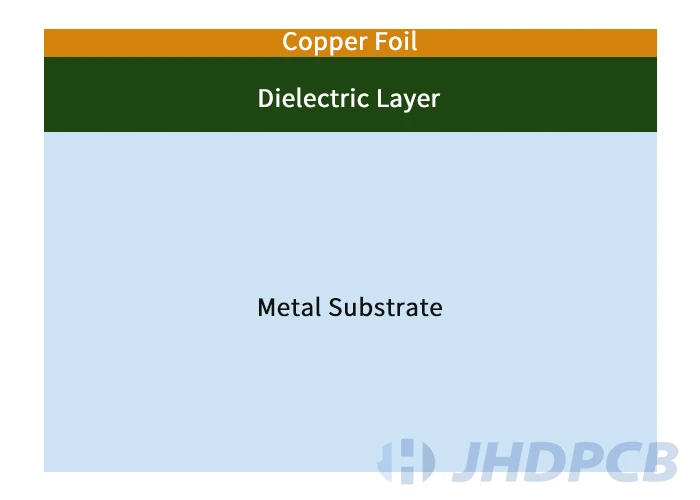
The thickness of copper foil is usually between 1oz and 12oz, of course, very thick copper is also used in some special cases.
The thickness of the dielectric material acts as an isolation layer, and generally needs to be as thin as possible while maintaining insulation resistance control to maintain heat transfer functions. During the operation of the printed circuit board, the heat generated by the circuit and components is conducted to the metal substrate for heat dissipation. The higher the thermal conductivity of the dielectric layer, the higher the cost and the higher the heat transfer effect.
The metal backplane is the thickest material in the MCPCB. Provide rigidity to the entire board and keep the plane flat. Reasonable thickness ensures component installation compatibility. The normal thickness is between 1-3.2mm.

Copper Foil (µm)35-420
Dielectric Thickness (µm)70-210
Dielectric Thermal Conductivity(W/mK)1-3
Thermal expansion coefficient (µm/m-°C)15-25
Metal core thickness (mm)1-3.2
Metal core typeAluminum, Copper, Steel Alloys

MCPCB structure

Plated Through Holes for Metal Core PCBs:

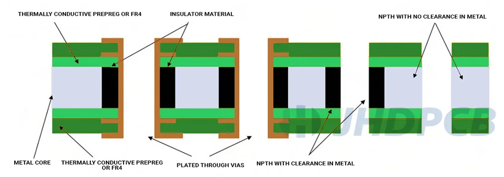
Due to the high heat dissipation of metal core PCBs, the need for heat dissipation through vias is reduced. The workload of drilling holes in the manufacturing process is reduced. Use SMT assembly as much as possible in the packaging design process of metal core PCB components. Reduced plated through-hole component mounting methods. Due to the conductivity of the underlying metal backplane, the leads of the plug-in conductive elements can cause short circuits. View detailed knowledge of through-hole assembly techniques. If PTH cannot be avoided, a more cumbersome process step needs to be added:

  1. Insulate the metal backplane from the vias with a non-conductive epoxy fill. Therefore, the diameter of the through hole in the metal core needs to be about 50 mils larger than the expected plated through hole;
  2. Remove excess epoxy resin filling compound on the surface;
  3. Drill plated through holes immediately after laminating the inner layer board;
  4. The follow-up process implements the standard circuit board manufacturing process;

Plated Through Holes for MC PCBs

Laminate structure type of metal core PCB:

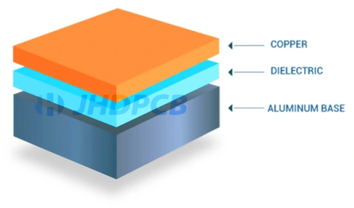
Single Layer MC PCB: This is the most common type of MC PCB. The single-layer copper foil layer is formed by pressing the dielectric material and the metal substrate.

Single Layer MC PCB

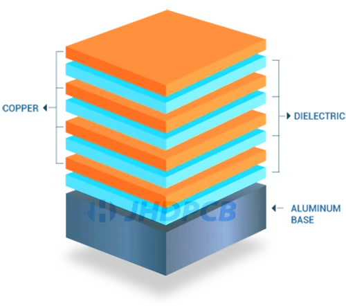
Multilayer MC PCB: Multi Layers MC PCB has more than two conductive layers, and each layer of copper foil corresponds to a thermally conductive insulating dielectric layer. All layers are on one side of the metal substrate. Electronic components should only be placed on one side, avoiding the use of THT components. Blind and buried vias can be used for internal power and signal layers, but through-hole processing should be avoided as much as possible. The process is relatively complicated, and it is recommended to consult JHD’s customer service staff in advance.

Multilayer MC PCB

Double Sided MC PCB: Double Sided MC PCB has two layers of copper conductors. The copper foil sandwiches the metal core in a symmetrical manner(insulation treatment is required for vias). The top and bottom copper layers can be connected by vias. Electronic components can be distributed on two layers of the board. This lamination method can effectively avoid the problem of warping in the later stage.

Double Sided MC PCB

What is the difference between Mcpcb and FR4 PCB?

Sometimes we are entangled in how to choose between MCPCB and FR4 PCB. But it is not difficult, we summarize the knowledge for your reference. You can choose according to your project needs, or send PCB related design files to JHD. We will check for free and give the best advice.

Thermal Conductivity: The thermal conductivity of FR-4 PCB is low, generally around 0.3W. Controlling the thinness of the dielectric material as much as possible helps the metal core laminate to spread heat faster and achieve heat dissipation. The heat transfer speed of MCPCB can reach 8-10 times that of FR4 PCB. While the thermal conductivity of MCPCB is higher, it is between 1.0W/m.k and 10W/m.k, and the most common one is 2.0W/m.k or 3.0W/m.k. JHDPCB can produce 10W/m.k aluminum PCB with cost performance.
Layers: FR-4 PCBs are available in multi layers application, but metal core PCB usually only have 1-2 layers, maximum is 4 layers. Therefore, metal PCB is not suitable for products with complex circuit design.
Plated Through Holes(PTH): Usually, The Through Hole can be drilled directly in FR4 and plated with copper without additional process. It can be use plug in through hole components if required. In metal core PCB, a layer of resin needs to be plated first before plated. All components are surface-mounted.

Comparison of Metal Core PCB and FR4 PCB
ParametersMC PCBStandard FR4 PCB
ThicknessThickness variations are limited. Depends on the available backing plate thickness and dielectric sheet thicknessWide range of thicknesses available
ConductivityHigher thermal conductivity, typical values – 1W/mK to 7W/mKLow thermal conductivity, typical values – 0.3W/mK to 0.4W/mK
Plated through-holePTH not available in 1-layer PCB. Components are surface-mountedImplements PTH
Thermal reliefMetal cores dissipate heat quickly. Eliminates vias for heat transferHeat transfer rate is lower. Involves vias for heat transfer
SoldermaskWhite color for LED boards. Applied only on the top layerIncludes dark colors like green, red, blue, and black
Machining processInvolves the same standard process except that the v-scoring process incorporates diamond-coated saw blades for cutting through metal.Standard machining process that includes drilling, routing, v-scoring, countersink, counterbore.
EconomyRelatively expensive than FR4 boardsLess expensive
RigidityAbility to handle shock and vibration. 2 to 4 times stiffer than FR4 or polyimide designs.Lesser rigidity compared to metal core

Metal Core PCB Design and Manufacturing Guide.

Metal core PCBs require the implementation of certain specific design guidelines to ensure compliance with manufacturing process requirements. The following will walk you through the guidelines you should follow in your design to ensure your MC PCBs meet industry standards.

  • Any electronic components should be placed on the opposite side of the metal backplane;
  • Buried and blind vias can be used to connect between copper foil trace layers, but not on metal substrates;
  • Before the multi-layer MCPCB (whether double-sided symmetrical or single-sided backplane) is stacked, the metal core needs to be punched in advance and plated with an insulating layer. avoid short circuits;
  • Epoxy-filled isolation is required to avoid short circuits when performing plated through holes on double-sided metal core PCBs;
  • The metal layer should be grounded to provide better shielding;
  • In the aerospace and military fields, it is also necessary to fix the metal core of the MC PCB on the shell;
  • Metal core PCB should use SMT surface mount electronic components as much as possible;
  • Select the appropriate material for the metal core to avoid the interaction of the metal backing with chemicals and other metals in the production process;

Application areas of MCPCB.

Due to the many advantages of metal core PCB, it is widely used in various industries. Some common application areas are as follows:

  • LED – Backlight unit, general lighting;
  • Automotive – Motor Control for Electric/Hybrid Vehicles;
  • Motor driven;
  • Solid state relay;
  • Power Equipment – Regulators, Switching Regulators, DC-DC Converters;
  • Solar panels, photovoltaic cells;
  • Sport control;
  • Semiconductor thermal insulation board;
  • Audio amplifier;

Why choose JHD as your MCPCB manufacturer?

JHDPCB is one of the top five MCPCB manufacturers in China, and we have been committed to providing customers with cost-effective and high-quality metal core PCBs. We have a full set of automated production equipment and precision testing equipment for metal PCB (aluminum-based PCB, copper-based PCB) production. Over the years, we have been focusing on the R&D and manufacturing of metal circuit boards, Years of experience in MCPCB manufacturing. We can be your best source for buying Metal core PCB boards when you need them.
JHD has been deeply involved in the field of metal core PCB for many years and has rich production experience. In terms of materials, regardless of the aluminum substrate, thick copper plate or steel composite plate, it has the best production cost control advantages. In terms of stacking, whether it is single-sided MC PCB, double-sided MC PCB, and multi-layer MC PCB, we can provide you with the best executable DFM solution. Here are some common specifications for JHD to produce MC PCBs:

Common Specifications for JHD Manufacturing MC PCB
Name Parameter Description
Layers 1-12 Layers Maximum Layers
Laminate suppliers Bergquist, polytronics, boyu /
Copper Foil (µm) 15-420 Circuit copper foil thickness
Trace width (mm) 0.15 Minimum trace width
Trace spacing (mm) 0.15 Minimum trace spacing
Dielectric Thickness (µm) 70-300 Dielectric Material Thickness
Dielectric Thermal Conductivity (W/mK) 1-4 Thermal conductivity of dielectric materials
Metal core thickness (mm) 0.4-3.2 Metal base thickness
Metal Core Type Aluminum, Copper, Steel Alloys Metal core material type
Through Hole Diameter (mm) 0.2 Minimum Through Hole Diameter
Hole diameter (mm) 0.5 Minimum diameter of turning hole
Hole Tolerance (mm) +/-0.05 Npth Hole Tolerance
Hole pitch (µm) 250 Minimum hole pitch
Annular Ring (µm) 125-200 Minimum Annular Ring
Aspect ratio 10:1 Maximum Aspect Ratio
Dam (mm) 0.1 /
Clearance (mm) 0.05 /
Peel Strength >9lb/in /
Solder resistance SF: 288°C, >180 seconds /
Combustibility UL 94V-0 Flammable rating

The above are our usual metal core PCB manufacturing specifications, but are not limited to this. We can make adjustments according to your design needs. To learn more about our advantages, visit Why choose JHDPCB.
Let us know when you need metal core PCB. Our customers rely on us to deliver on time. JHDPCB has been committed to providing PCB products to various companies in Fortune 500 companies or start-ups.