decoupling capacitor vs bypass capacitor

Decoupling capacitors and bypass capacitors in PCB.

directory

Decoupling capacitors are an integral part of any PCB design as they help to mitigate noise and stabilize voltage levels. These capacitors are strategically placed near integrated circuits (ICs) to provide a low-impedance path for high-frequency noise generated by the ICs. By reducing noise, decoupling capacitors enhance the overall performance and reliability of electronic devices. At JHDPCB, we understand the criticality of decoupling capacitors and employ advanced manufacturing techniques to ensure their precise placement and reliable functionality within our PCBs.
Similarly, bypass capacitors also contribute to the optimal functioning of PCBs by minimizing noise and maintaining voltage stability. These capacitors serve as local energy reservoirs, storing and releasing energy when needed, thereby maintaining a steady supply of power to sensitive components. By eliminating voltage fluctuations, bypass capacitors enhance the signal integrity and reduce the risk of malfunctions or damage to the circuitry. At JHDPCB, we recognize the importance of bypass capacitors and incorporate them into our PCB designs with meticulous attention to detail.

Our commitment to delivering superior PCB manufacturing services extends beyond mere component integration. At JHDPCB, we boast state-of-the-art facilities, cutting-edge technology, and a highly skilled team of professionals who work tirelessly to ensure the highest quality standards in every PCB we produce. Whether it’s a complex multilayer design or a compact single-layer board, we possess the expertise to handle diverse requirements while adhering to strict quality control measures.
In this article, we will delve deeper into the role of decoupling capacitors and bypass capacitors in PCBs, exploring their functions, benefits, and best practices for their implementation. We will showcase JHDPCB’s proficiency in incorporating these crucial components into our PCB manufacturing process, underscoring our commitment to delivering reliable and efficient PCB solutions.

What is a decoupling capacitor?

A decoupling capacitor, also referred to as a bypass capacitor or power filter capacitor, is an electronic device used to mitigate or eliminate noise and voltage variations in electronic circuits.
In electrical circuits, elements are energized by a source of electricity or voltage stabilizer. However, the circuit’s intrinsic characteristics and the presence of other components can cause deviations in the supplied voltage, resulting in circuit noise and interference that can lead to reduced performance or malfunction.

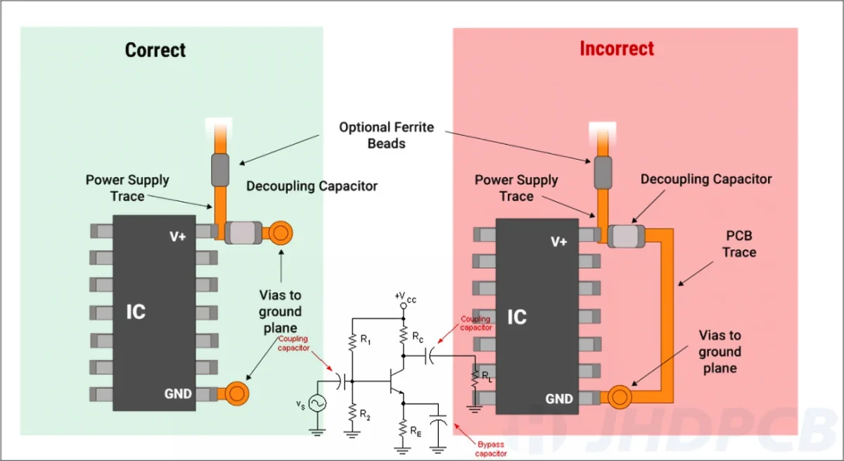
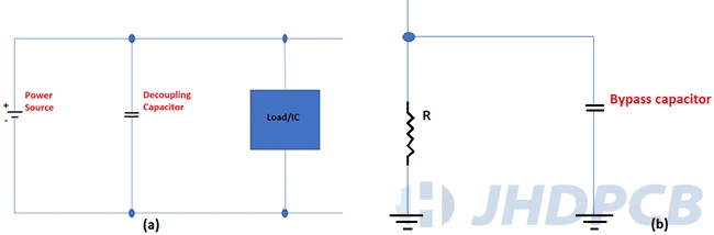
A decouple capacitor is positioned in parallel with the power source or voltage regulator, serving as a low-impedance channel for high-frequency noise and voltage deviations. In the case of a voltage regulator, a voltage regulator decoupling capacitor is placed in parallel with the regulator to ensure that the output voltage is free from fluctuations caused by high-frequency noise.It functions as a shield that absorbs any voltage surges or drops, ensuring a stable voltage supply to the components while minimizing electromagnetic interference (EMI) and radio frequency interference (RFI) in the circuit.

decoupling capacitor

Decoupling capacitors are often employed in digital circuits, microprocessors, and other high-speed electronics. They come in various types and values, with the specific choice based on the circuit requirements. Ceramic, tantalum, and aluminum electrolytic capacitors are among the most common decoupling capacitor types.
In summary, decoupling capacitors are critical electronic circuit devices, ensuring stability and reliability by mitigating noise and voltage fluctuations.

What does a decoupling capacitor do?

As the core material of PCB, the three main raw materials for the production of CCL include glass fiber cloth, epoxy resin and copper foil, and PCB relies on them to realize the functions of conduction, insulation and support. Among them, glass fiber cloth and epoxy resin are often used as prepregs.

The primary function of the bypass capacitor is to eliminate or reduce high-frequency noise, such as the RF signal, that infiltrates the device via electromagnetic radiation.
Furthermore, the capacitor positioned near the chip also serves as an energy reservoir. Imagine that the main power supply is a tank, and each household in our building requires a water supply. The water does not flow directly from the tank since it is too far away, and we need to wait a long time until the water arrives. The actual water supply comes from the rooftop water storage tank, which acts as a buffer.
At the microscopic level, when a high-frequency device operates, its current is not continuous due to the high frequency and distance between the device VCC and the main power supply. Even if the distance is short, at high frequency, the impedance and inductance of the line will be significant, resulting in a delay in the current supply to the device. The decoupling capacitor can compensate for this delay, which is why many small capacitors are placed at the VCC pins of high-frequency devices on circuit boards.

When switching the active components on and off, high-frequency noise is generated and transmitted through the power line. The primary decoupling capacitor purpose is to furnish a nearby local DC power to the active components, thereby minimizing the spread of switching noise across the board and directing the noise towards the ground.

Decoupling capacitors not only mitigate high-frequency noise but also mitigate voltage fluctuations in electronic circuits. A device’s sudden demand for a large amount of current can cause a drop in the power supply voltage, resulting in malfunction or even damage to the device. Decoupling capacitors act as a reservoir of stored energy, compensating for these sudden changes in current demand and maintaining a stable voltage supply to the device.

Decoupling capacitors also have an important role in enhancing signal integrity in electronic circuits. When a signal travels through a circuit, it may become distorted by noise and interference. Decoupling capacitors help filter out unwanted noise and interference, enabling the signal to pass through the circuit more accurately and effectively.

Decoupling capacitors can additionally contribute to preventing interference between different components in a circuit. Interference occurs when signals from one component interfere with signals from another component, leading to errors and malfunctions in the circuit. Decoupling capacitors act as a barrier or shield, blocking unwanted signals from interfering with other components and improving the overall performance of the decoupling capacitor circuit.

Coupling capacitors are utilized to allow AC elements to pass while blocking DC elements. Meanwhile, decoupling capacitors serve as energy reservoirs in electronic circuits to prevent rapid voltage adjustments, and bypass capacitors are employed to divert undesirable AC elements to the ground, thereby cleansing DC signals. In summary, decoupling capacitors are vital components in electronic circuits that reduce high-frequency noise, maintain a stable DC power supply, mitigate voltage fluctuations, enhance signal integrity, and prevent interference. They are essential elements in guaranteeing dependable and effective functionality of electrical devices.

How to Use Decoupling Capacitors?

Decoupling capacitors are employed in electronic circuits to minimize noise and fluctuations in voltage. They are ordinarily situated between the power source and ground and contribute to steadying the voltage at the IC or component that is being powered. Below are some guidelines for utilizing decoupling capacitors:

  • Choose the appropriate capacitor type: Decoupling capacitors should have high capacitance values and low ESR (Equivalent Series Resistance). Ceramic capacitors are a popular choice for decoupling since they have low ESR and are available in high capacitance values.
  • Position the capacitor in close vicinity to the IC: The capacitor for decoupling must be positioned in immediate proximity to the IC or component receiving power. This minimizes the length of the power traces, which can act as antennas and pick up noise.
  • Use multiple capacitors: Using multiple decoupling capacitors of varying values can help to filter out a wider range of frequencies. For instance, you could use a 0.1uF ceramic capacitor in conjunction with a 10uF tantalum capacitor.
  • Implement a ground plane: A ground plane can provide a low-impedance ground connection for the decoupling capacitor. This is particularly crucial for high-frequency circuits.

By following these guidelines, one can effectively utilize decoupling capacitors to reduce noise, improve power supply stability, and enhance the overall performance of electronic circuits.

What is a Bypass Capacitor?

Bypass capacitors are essential constituents of electronic circuits, and they perform a critical function in filtering out AC noise from DC signals. They achieve this by connecting between the VCC and GND points of integrated circuits, forming an expedient path to ground that circumvents noise. Capacitors serve as highly effective filters that remove noise caused by various devices and components present within the system.

Bypass Capacitor

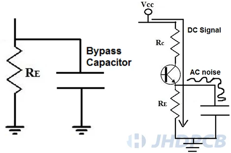
In operation, bypass capacitors provide a pathway of minimal resistance for AC signals to ground, enabling the delivery of pure DC signals. For example, in a transistor circuit, the bypass capacitor eliminates AC ripple effects from the DC voltage to guarantee that the transistor receives pure DC signals to amplify. Many DC power sources, such as power supplies, often emit unwanted AC noise and current surges that can introduce undesirable interference into electronic circuits. By using a bypass capacitor, circuit designers eliminate the noise, ensuring that only clean DC signals are delivered to active components.
Furthermore, bypass capacitors offer high impedance to low-frequency signals like DC signals, but their impedance is much lower towards high-frequency signals like AC signals. This functionality enables AC noise to travel through the capacitor and reach the ground while transmitting the DC signal through the resistor. Designers incorporate bypass capacitors within electronic circuits to guarantee that the circuits operate solely on clean and noise-free DC signals.

In brief, bypass capacitors are crucial components in contemporary electronics because they filter out unwanted noise from DC signals. They function by directing AC noise to the ground while enabling clean DC signals to pass through. Designers of electronic circuits must exercise caution when selecting bypass capacitors to ensure optimal performance and minimal noise.

What is the difference between a bypass capacitor and a decoupling capacitor?

Decoupling capacitors and bypass capacitors can serve as anti-interference components in electronic circuits, but they are positioned differently. In the same circuit, the bypass capacitor removes high-frequency noise carried by the previous stage circuit from the input signal. On the other hand, the decoupling capacitor eliminates interference from the output signal and prevents the interference signal from being reflected back to the power supply. This is the fundamental distinction between them.

Decoupling Capacitors vs Bypass Capacitors

The decoupling capacitor stores energy and releases it back into the power supply to maintain a steady current flow. The bypass capacitor offers a path for the AC signal to return to switch between the power and ground rails. Both bypass and decoupling capacitors are interchangeable because of their shared purpose and function. The primary objective when energizing any device is to establish a low-impedance pathway in relation to the input power ground. However, there are a few noticeable differences:

  • Bypass capacitors are utilized to provide a low impedance path for high-frequency noise signals. They ensure that high-frequency noise is suppressed before it spreads throughout the entire circuit, which could cause circuit malfunction and EMI issues. Conversely, decoupling capacitors are utilized to stabilize voltage variations.
  • For low impedance bypassing, a solitary electrolytic capacitor would suffice, but for signal stabilization, the utilization of two dissimilar capacitor types is imperative.

How to choose a decoupling capacitor?

The quantity of decoupling capacitors required in a circuit is subject to the number of ground and power pins, as well as the current I/O signals. In addition, the appropriate decoupling capacitor selection should also be taken into consideration. It is recommended to select a capacitor type that possesses adequate self-resonant frequencies appropriate for the operational frequency or signal bandwidth.

self-resonant frequency

Until it reaches the self-resonant frequency, a decoupling capacitor maintains its capacitive properties, after which it converts to an inductor. At this specific frequency, the impedance of the component drops to its minimum value. Diminishing the capacitance and inductance will result in an increased resonant frequency. Surface-mount miniaturized components have reduced parasitic inductance, leading to an augmented self-resonant frequency.
It is preferable to use a low-frequency decoupling capacitor with a value ranging between 1-100 µF. In contrast, noise decoupling capacitors are recommended to contain values ranging from 0.01-0.1 µF suited for high-frequency applications. Remember to take into consideration the factors mentioned below:

  1. ESR and ESL: Equivalent Series Resistance (ESR) and Equivalent Series Inductance (ESL) are important factors to consider when selecting a capacitor. To ensure that the capacitor can provide instantaneous current, it is preferable to select one with low ESR and ESL values.
  2. Package Size: The utilization of miniature capacitors reduces the loop size, leading to a reduction in loop inductance. 

1. Digital Power Delivery Network(PDN)
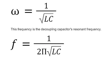
To reduce noise and fluctuations, it is crucial to place the capacitor accurately and determine its exact size based on the impedance of the power delivery network and the charge required by the switching IC. A formula is needed to perform the necessary calculations.

PDN formula

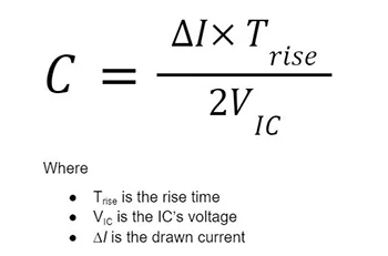
However, it’s important to note that this equation is only applicable if the signal bandwidth doesn’t surpass the self-resonance frequency. 

2. Analog power delivery network (PDN)
In an analog PDN, the decoupling capacitor must recharge and discharge continuously to ensure stable power for an analog IC. The following formula determines the size of the capacitor required for this analog configuration.

PDN formula2

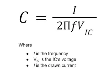
The magnitude of current drawn is a function that shows an increase concerning the frequency and voltage of the IC.

3. PDN Impedance
Decoupling capacitors function optimally within a specific frequency range. The impedance of the capacitor diminishes linearly as the frequency increases, and vice versa is also true. Parasitic inductance gives rise to an augment in impedance. 
To establish the size of a decoupling capacitor, you may employ the following formula based on the intended PDN impedance:

PDN impedance formula

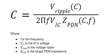
The ripple voltage in a PDN and the target PDN impedance are both dependent on the capacitance. Therefore, solving this problem can be complicated as it requires multiple iterations to calculate the capacitance accurately.
However, the formula mentioned above is precise because it takes into account the decoupling capacitor’s resonance frequency effect, which arises due to parasitics. When calculating different target PDN values for capacitance and frequency, the optimal capacitance value can be determined to achieve the lowest target PDN across all frequency ranges.

The primary function of a decoupling capacitor is to maintain voltage levels within specified limits, regardless of current fluctuations and regulations.

Method 1: Capacitance C required for the decoupling capacitor can be computed using the formula:
               C .⊿U = I .⊿t
Where ⊿U represents the allowable decrease in actual power bus voltage (V);
I denote the maximum current requirement (A);
⊿t is the duration time for which the capacitance is required.

Method 2: A recommended value for the decoupling capacitor is greater than 1/m times the equivalent open-circuit capacitance. Here, m represents the highest percentage of allowable changes in the power bus voltage on the IC power supply pin, which is typically provided in the IC datasheet.
The equivalent open-circuit capacitance can be calculated as follows:
              C= P/(f.U ^2)
Where P signifies the total wattage dissipated by the IC;
U denotes the maximal DC power supply voltage of the IC;
f represents the clock frequency of the IC.

After determining the equivalent open-circuit capacitance, the total value of the decoupling capacitor required by the IC is obtained by multiplying it by 1/m. The outcome is then divided by the total number of power pins attached to the same power bus, resulting in the capacitance value close to all power pins connected to each power bus.

How to choose the value of the bypass capacitor?

When adding a capacitor to a circuit, the reactance of the capacitor must be no more than 1/10th of the parallel resistance. As current prefers to travel through the path with the least resistance, a capacitor with a lower resistance is necessary to shunt the AC signal to the ground. To determine the capacitance value for the bypass capacitor needed, utilize the following formula:
            C = 1/2πfXC
Suppose you must determine the capacitance of a capacitor connected to a resistor with a resistance of 440Ω. We know that the reactance must always equal 1/10th of the resistance, implying a reactance value of 44Ω. Also, it should be noted that the normal operating frequency of the electrical power grid in India is 50 hertz. Therefore, you may calculate the bypass capacitor’s capacitance using the formula below:
            C = 1/2(3.14)(50)(44)
Based on the formula provided earlier, the calculated capacitance of the capacitor connected to the 440 Ω resistor is 73µF. This capacitance value can be used as a reference to determine the appropriate capacitor(s) to use in a circuit. 

Where to place decoupling capacitors?

To achieve efficient decoupling capacitor placement, decoupling capacitor layout should follow the following guidelines:

  • It is advisable to position the capacitor in immediate proximity to the source signal it is intended to decouple.For ICs, this entails positioning the capacitor at the pin, while for input and output signals, it should be located near the connector.
  • To eliminate low-frequency transients from input and output signal paths, it is recommended to connect the capacitor in-line with the trace. By doing so, the capacitor permits high-frequency signals to pass while blocking low-frequency and DC signals. The use of small capacitors is recommended for high-frequency transients, while large capacitors are suitable for low-frequency transients.
  • When dealing with power pins and grounds, the goal is to eliminate AC or couple DC for power distribution and grounding. Hence, it is advisable to connect the capacitor in parallel with the signal path.
  • In addition, decoupling capacitors can be connected in parallel with resistors to filter out undesired high-frequency signals while permitting low-frequency and DC signals to pass.
  • To guarantee that current passes through the plane when utilizing vias to reach the power plane, it is suggested to first connect the capacitor to the component pin, and then to the via.
  • Isolating analog and digital returns is feasible with decoupling capacitors. One way to achieve this is by linking a capacitor between the AC and digital ground pours on the same layer of the PCB.

In addition to proper placement, effective decoupling for power supplies on multisignal boards also requires the application of sound grounding practices. In the case of ICs with BGAs, it might be necessary to use dogbone routing and vias in order to integrate decoupling capacitors. Nevertheless, if the power and ground connections are located adjacently on internal balls, it is feasible to establish a direct connection to the power and ground planes by the use of microvias.

What types of capacitors are used for decoupling?

Functional Classification:

Decoupling capacitors are essential components of electronic circuits that aid in stabilizing the power supply voltage. They can be classified into three types: global, local, and inter-board decoupling capacitors.

  • Global decoupling capacitors operate in the low-frequency range and provide a single current source for the entire circuit board to compensate for the noise generated during operation. Their capacitance is usually 50 to 100 times the sum of all load capacitances on the PCB. It is recommended to place them near high-density printed lines of power and ground wires on the PCB to ensure low-frequency decoupling without affecting the placement of critical printed lines.
  • Local decoupling capacitors serve two functions: stabilizing the power supply voltage obtained by the integrated chip and providing an adjacent high-frequency channel for the transient current of the integrated chip. This reduces radiation noise while suppressing impedance coupling. The local decoupling capacitor is positioned as close as possible to the chip between the power supply terminal and the ground terminal of each integrated chip.
  • Inter-board decoupling capacitors are located between the power plane and ground plane and represent the primary source of decoupling current at high frequencies. Capacitance between the planes can be increased by enlarging the area between the power layer and the ground layer. Replacing some ground planes with power isolation areas can also help increase the capacitance between the planes.
  • Capacitors utilized for high-frequency decoupling: These capacitors serve to eliminate high-frequency interference that may disrupt the functioning of delicate electronic components. They usually have a low capacitance value and are relatively small in size.
  • Capacitors employed for low-frequency decoupling: These capacitors are designed to eradicate low-frequency noise that can result in power supply instability. They typically possess a higher capacitance value and are generally larger in physical dimensions.

Material Classification:

In terms of materials, there exist numerous types of capacitors that are utilized for decoupling purposes:

  • Ceramic capacitors: These capacitors are frequently utilized for high-frequency decoupling as a result of their low inductance and high stability. They can be obtained in a diverse range of capacitance values and can be either surface-mounted or through-hole. Apart from their application in high-frequency decoupling, ceramic capacitors are frequently utilized for signal coupling and filtering in electronic circuits. They possess a low dissipation factor, which renders them beneficial for circuits requiring minimal energy loss. Additionally, ceramic capacitors exhibit high tolerance to operating temperatures, which makes them appropriate for deployment in high-temperature settings.
  • Tantalum capacitors: These capacitors find common use in low-frequency decoupling applications due to their high capacitance value and low ESR (Equivalent Series Resistance). They come in both surface-mounted and through-hole packages.Tantalum capacitors are classified as polarized capacitors, implying that they must be appropriately connected to a circuit with the correct polarity. They possess high capacitance density and exceptional volumetric efficiency, making them a fitting option for deployment in small electronic devices like laptops and smartphones. Nevertheless, tantalum capacitors are vulnerable to voltage spikes and may suffer damage if exposed to excessive voltage or current.
  • Aluminum electrolytic capacitors: These capacitors see common usage in low-frequency decoupling applications because of their low cost and high capacitance values. They are typically polarized and available only in through-hole packages. Aluminum electrolytic capacitors feature a moderately elevated ESR (Equivalent Series Resistance) in contrast to other categories of capacitors, which renders them less than ideal for high-frequency applications. They also possess a finite lifespan and are prone to deterioration over time, which may adversely impact their functionality within the circuit. Nevertheless, aluminum electrolytic capacitors are reasonably priced and widely accessible, which contributes to their popularity as a preferred option for low-frequency decoupling tasks.
  • Film capacitors: These capacitors are employed for both high and low-frequency decoupling requirements and come in a wide range of capacitance values and voltage ratings. Normally, they are more expensive than ceramic or electrolytic capacitors and are offered in both surface mount and through-hole types of packages.Film capacitors can be produced utilizing diverse materials, like polyester, polypropylene, and polycarbonate. They boast remarkable insulation resistance and stability across an extensive gamut of temperatures and frequencies. Film capacitors are employed in circuits necessitating high precision and negligible losses, for instance, audio equipment and power supplies. High-voltage film capacitors are also accessible, and they can endure high operating temperatures, rendering them fitting for deployment in stringent environments.
Type of CapacitorFunctionMaterialCommonly Used For
High-frequency decoupling capacitorFiltering out high-frequency noiseCeramicSensitive electronic components
Low-frequency decoupling capacitorFiltering out low-frequency noiseTantalum, Aluminum electrolyticPower supply fluctuations
Ceramic capacitorLow inductance, high stabilityCeramicHigh-frequency decoupling
Tantalum capacitorHigh capacitance value, low ESRTantalumLow-frequency decoupling
Aluminum electrolytic capacitorHigh capacitance value, low costAluminumLow-frequency decoupling
Film capacitorWide range of capacitance values and voltage ratingsFilmBoth high and low-frequency decoupling

What factors affect PCB decoupling capacitors?

Decoupling capacitors on a PCB are indispensable for minimizing noise and ensuring that integrated circuits on the board receive stable voltage levels. When designing a PCB, it is necessary to take various factors influencing decoupling capacitors into account.

  • Capacitance Value: The capacitance rating of a decoupling capacitor is essential as it determines the amount of energy that the capacitor can store or release. It is crucial to choose the appropriate capacitance rating that matches the circuit’s requirements. A capacitor with an insufficient capacitance rating may not provide adequate filtering, while one with an excessive capacitance rating may result in unfavorable impacts due to longer charging/discharging times and increased circuit time constants.
  • Frequency Response: The decoupling capacitor frequency characteristic is critical because it affects the capacitor’s ability to filter out noise. Ceramic capacitors exhibit lower impedance across a broad frequency range and are beneficial for filtering high-frequency noise. Tantalum and electrolytic capacitors have a narrower frequency range, making them more suitable for lower frequency noise.
  • ESR (Equivalent Series Resistance):ESR is a significant consideration when selecting the capacitor type for decoupling. Tantalum capacitors have low ESR, making them suitable for analog circuits. In contrast, ceramic capacitors have higher ESR, making them more effective for high-frequency digital circuits.
  • Temperature Rating: The temperature rating of a decoupling capacitor is also a crucial factor to consider when choosing the capacitor. The operating temperature range of the PCB must fall within the capacitor’s specification to ensure dependable performance and prevent failure.
  • Dimensions: The physical dimensions of a capacitor are another consideration when designing a PCB layout. Capacitors come in different sizes, and selecting the appropriate size will depend on the amount of space available and the required capacitance level.
  • Voltage Rating: The voltage rating of a decoupling capacitor can impact its performance in several ways, such as selecting an appropriate voltage rating to prevent breakdown, taking into account capacitance variation and increased leakage current at higher voltages, and also considering possible dielectric breakdown at extremely high voltages.

In conclusion, the primary factors to consider when choosing a decoupling capacitor for a PCB design include capacitance value, frequency response, ESR, temperature rating, physical size, and PCB voltage rating.

Bypass capacitors and decoupling capacitors play important roles in electronic circuit design. As a PCB supplier, JHDPCB provides high-quality circuit boards that can be used by circuit designers to better implement circuit functions. The efficient and reliable supply service of JHDPCB can also help customers quickly obtain the required circuit boards, save time and cost for customers, and better realize the competitive advantage of products. Welcome to contact us, we will improve the high quality of service for you!

A common purpose of adding an AC decoupling capacitor is to transmit an AC audio frequency signal from an amplifier’s output to a speaker while preventing the DC supply from reaching the speaker voice coil.
It is also applied to connect audio/radio frequency signals between amplification stages while isolating DC between stages to facilitate biasing and other operations.
The chief aim of an audio decoupling capacitor usually is to isolate unwanted signals from power supply rails or among stages in multi-stage circuits for audio frequency, radio frequency or some other purpose.

Decoupling capacitors are commonly connected in parallel to the signal path and applied to eliminate the AC component. In contrast, coupling capacitors are connected in series with the signal path and used to remove the DC portion of a signal. They find application in both digital and analog circuit systems.

Bypass capacitors are frequently mounted between the VCC and GND terminals of an integrated circuit to reduce the occurrence of voltage spikes on the power supply and mitigate power supply noise.As it filters out high-frequency elements of the power supply, this type of capacitor is referred to as a “bypass” capacitor.

Bypass capacitors are employed to sustain a low power supply impedance at the load point. Because parasitic resistance and inductance in supply lines can cause high power supply impedance, this becomes particularly problematic as frequency increases with inductive parasitics.

Coupling capacitors (or DC blocking capacitors) are employed to isolate AC and DC signals in order to avoid upsetting the circuit’s quiescent point when AC signals are introduced at the input. Bypass capacitors are utilized to direct signal currents around components by supplying a low impedance path at the given frequency.

Decoupling capacitors act as an energy reservoir and serve two functions in stabilizing voltage. Firstly, when voltage surpasses the rated value, the decoupling capacitor absorbs excess charges, while it releases those charges when voltage drops to maintain stable supply.

The best location for a bypass capacitor is as near to the component’s supply pin as possible. By being located in the immediate vicinity of the power supply pin, the bypass capacitor reduces the effect of current spikes that occur during switching while also creating a low impedance path to ground for AC noise signals.

Bulk capacitor smoothes out voltage fluctuations from input power source to stabilize DC voltage level, while decoupling capacitor isolates and reduces high-frequency noise generated by digital circuits.

Get a PCB Quote Now

Open high-quality PCB manufacturing services in JHDPCB

Leave a Comment