IPC Class

IPC Class Standards for PCB Manufacturing: Rule Definitions.

directory
directory

What is IPC?

IPC was founded in 1957 as the Institute of Printed Circuits. Founded in 1957 by 6 printed circuit board manufacturers, As more electronics assembly companies joined the association, the name was changed to the Institute for Electronic Circuit Interconnection and Packaging. It was renamed “Association Connecting Electronics Industries” in 1999 after a huge expansion, but still uses the abbreviation IPC.
IPC is the global association that helps OEM, EMS, PCB manufacturers, cable and harness manufacturers, and electronics industry suppliers better build electronics. IPC members strengthen their bottom line and build more reliable, high-quality products through proven standards, certifications, education and training, thought leadership, advocacy, innovative solutions, and industry intelligence.

Now the membership of IPC has expanded to more than 4,000 enterprises, and the IPC standards formulated by it have also been widely adopted and become a common standard in the electronics manufacturing industry. IPC standards cover every process of PCB design, procurement, production, assembly, testing and acceptance.

Why implement IPC standards?

To achieve safe, reliable, high-performance PCB products and maintain a competitive position in the market, you need to infuse quality throughout the manufacturing process. Constant attention to detail and commitment to quality. From design, procurement, production to assembly and acceptance, compliance with IPC standards throughout the process can help companies achieve this goal. IPC offers a number of standards to help you ensure excellent quality printed circuit boards. To achieve your desired results, implementing proper IPC standards associated with each production step can ensure board reliability and consistency.

Compliance with IPC standards throughout the manufacturing process helps improve manufacturing processes and helps companies increase the quality and reliability of their products. Using IPC standards when inspecting PCBs and other products ensures consistent quality. Ensure that the PCB has the expected performance and longer service life.

IPC standards are the standards used by customers, suppliers or EMS providers. Working to established IPC standards helps designers, manufacturers, assemblers, testers all speak the same language—the language of the global electronics industry. Improve internal and external communication, ensuring everyone is using the same terminology and agreeing on expectations. Uniform terminology prevents miscommunication, facilitates collaborative production, and makes it easier to make changes needed for improvement. IPC standards also improve communication with customers, suppliers, regulators and others.
Miscommunication can cause delays and inconsistencies in production and can lead to unhappy customers and significant losses.

The use of IPC standards can unify PCB design and subsequent manufacturing. Helps reduce costs. Improve quality and minimize the potential for delays, rework, and scrap due to miscommunication. IPC standards also enable companies to maximize control over resource usage and increase efficiency.

IPC standards will improve the quality of your products and enhance your reputation. Creating products that perform better and last longer will help increase a company’s competitiveness and profitability, as well as increase customer satisfaction. JHD strictly abides by IPC standards in every link, so as to be responsible to our customers. We manufacture high-quality products on their behalf, and they in turn can reassure their own end users that the product will perform well.

IPC standards help companies customize standardized product development, approval and traceable training programs. Help each employee understand the motivation and goals of manufacturing technology. To improve the skills and abilities of employees to an acceptable level of workmanship. At the same time, strengthen the control of product quality.

What IPC standards are there for the PCB production process?

PCB manufacturers must always adhere to a large number of IPC standards. There are many types of IPC PCB. For example: IPC-2221 for early design, IPC-A-6012 for the most widely used and highest acceptance, and IPC-A-600 for product acceptance. etc. The standards of IPC Class have specific items. Below we list some commonly used standards for PCBs:

  • What is IPC-2221? IPC-2221 is the most commonly used PCB process standard guide in the IPC 2220 design standard series. In the 2220 series, there are also IPC standards for flexible PCBs, as well as standards for rigid and MCM-L PCB. IPC 2221 Class 3 is also useful. IPC-2221 covers topics such as design layout, parts list, materials, mechanical and physical properties, electrical properties, thermal management, and more.
  • What is IPC-2222? IPC-2222 details the criteria for rigid organic circuit boards, including material selection, mechanical properties and hole size.
  • What is IPC-4101? IPC-4101 covers the requirements of substrate selection, commonly referred to as laminates or prepregs, and is mainly used for rigid printed sheets or multilayer boards. It concerns the materials used, their size and characteristics.
  • What is IPC-2581? IPC-2581 is a common standard used when sending information between PCB designers and manufacturers or assembly companies. It provides a standardized format for exchanging design data and helps ensure consistent production results.
  • What is IPC-6011? The IPC 6011 guidelines establish general requirements for PCBs and outline the quality and reliability levels they must meet. These involve design, assembly, testing and inspection.
  • What is IPC-6012? IPC-6012 establishes qualification and performance specifications for rigid printed boards. It also defines performance and qualification requirements for HDI and passive/active PCBs. It provides requirements for rigid PCB processes in various materials in the areas of structural integrity, solderability, and conductor spacing.
  • What is IPC-A-600? IPC-A-600 establishes acceptance criteria for PCBs. It describes the acceptable and non-compliance rules for all observable and non-visual conditions of the board. Such as: pads, gold fingers, copper plating, and other PCB reliability factors.
  • What is J-STD-001? The IPC J-STD-001 standard describes materials, methods, and verification criteria for creating high-quality soldered interconnects. Covers soldering materials, components and equipment; terminals and wire connections; cleaning and residue requirements as well as coatings, potting and adhesives.
  • What is IPC-A-610? IPC-A-610, Acceptability of Electronic Components, provides criteria for the acceptance of final products.
  • What is IPC-A-620? IPC-A-620 provides acceptable criteria for cables, wires, and wire harness assemblies as a stand-alone document for the purchase of products.
  • What is IPC-A-630? The IPC-A-630 is an Acceptability Standard for the Manufacture, Inspection, and Testing of Electronic Enclosures. It’s a simple standard that provides the requirements necessary for manufacturing, inspecting, and testing electronic enclosures.
  • What is IPC-TM-650? The IPC-TM-650 standard provides test guidelines for evaluating various aspects of PCBs. For example, test method IPC-TM-650 2.6.14.1 describes methods for testing the electrochemical migration tendency of circuit board surfaces. This test measures the resistance of current flowing through the PCB substrate surface. IPC-TM-650-2.3.25.1 describes an ion cleanliness test method for bare printed wire boards, which is important because ion contamination can cause problems that make PCBs defective.
  • What is IPC-1752? The IPC-1752 standard specifies requirements for the exchange of material and substance data between suppliers and their customers. 1752 provides basic supplier/requester details for necessary declarations between PCB supply chain members. These include: bare boards, bulk materials, assemblies.
  • What is IPC-7711? IPC 7711/7721 contains guidelines for rework, modification and repair of electronic assemblies. Its purpose is an introduction to hand soldering and rework, not a basic tutorial on hand soldering/rework. IPC 7711/7721 is intended for operators and technicians with basic knowledge and experience in circuit board rework and repair. The operator should have some rework and repair experience and good eye/hand coordination.

The above is the execution standards that IPCs are often used in the field of PCB manufacturing and assembly. You can choose the right series to help improve efficiency in combination with your role and needs.

Definitions of IPC Class 1 2 or 3.

When it comes to electronics manufacturing, PCBs are essential. In the production of electronic products, the IPC level of PCB is divided into three categories. Those are categories 1, 2, and 3. These categories really reflect the quality level of each board. These levels range from lowest (Level 1 standard) to highest (Level 3 standard).

  • CLASS 1 — General Electronics.
    The first electronic products class is referred to as the “general electronics” category. This consists of boards with the lowest quality requirements and is mostly found in products with an expected short life cycle. We can categorize class 1 products under the electronic boards’ group. These products have simple functions and a short lifespan. They comprise the day-to-day electronic product that we have at home and are easy to find. They include products such as TV remote control, LED lights, and children’s toys. Most of the products’ lifespan is relative to their cost.
  • CLASS 2 — Dedicated Service Electronic Products.
    Class 2 electronic devices encompass all electronics where continued performance and an extended life cycle is required — to a point. Uninterrupted service is desired, but not critical. This Class exhibits higher characteristics compared to class 1 boards. Class 2 boards have an extended lifespan and are more reliable. High reliability is important. IPC Class 2 soldering is very useful. IPC Class 2 serial data is also plentiful. To achieve this long lifespan and reliability, the products go through stringent standards in their manufacturing. Class 2 boards are not highly critical, and they run continuously. We find class 2 boards on devices such as tablets, communication equipment, laptops, and smartphones.
  • CLASS 3 — High Reliability Electronics.
    The third class of circuit boards are subject to strict guidelines due to their importance in the field. IPC Class 3 standard is useful. Whether it’s a pacemaker or a military radar, a product that needs to meet IPC Class 3 requirements must use high-reliability electronic components to ensure uninterrupted service. Boards manufactured is important. Electronics products are important. These are highly critical products that must continuously provide the required performance at all times. IPC Class 3 PCB manufacturing is fine. IPC Class 3 via sizes are diverse. Equipment with class 3 boards should not experience any downtime. IPC Class 3 soldering is useful. During the manufacturing process, the class 3 products undergo a high level of inspection to ensure that they are reliable and dependable. Equipment that uses class 3 boards includes electronic manufacturing systems, support systems, and military devices.
IPC Category Definition
 IPC Class 1IPC Class 2IPC Class 3
Life cycleShortLongVery long
QualityCheapGoodFailproof
CategoryGeneral electronicsDedicated service electronicsHigh-reliability electronics
ExamplesToys, flashlights, smartphones Laptops, Microwaves, and some mining equipmentAerospace, military, & medical applications

What are the common defects of IPC PCB?

Although IPC defines very comprehensive standards for PCB manufacturing and assembly. But there are still some defects worthy of our attention, especially in the field of high-precision applications.

Annular ring:
Annulr Ring is a process type that turns holes on the pad. Annulr Ring is a common defect in IPC PCB, and it is also a process that PCB designers are very concerned about. However, there are some acceptable standards (such as 90 degrees disconnection on the ring) in Class 2, which will not affect the performance of the circuit board.

Shorts:
Also called Solder Bridging, occurs when solder is improperly crossing and connects one lead to another. This can be microscopic in size and difficult to detect. If undetected, it can cause serious damage to the circuit assembly, like a burn-up or blow-up of a component and/or burn-out PCB trace.

Root CausesPrevention
Reflow profile error (initial ramp rate too steep).Ensure correct reflow profile.
Solder pads are too large relative to isolation between pads.Use appropriate solder past metal to flux weight ratio for the application.
Excess solder on pads due to incorrect stencil specification.Ensure paste deposition is in proper resolution and quality (noslump or smear) before reflow.
Inactive solder paste.Reduce stencil aperture dimensions by 10% or thickness of stencil toreduce amount of paste deposited.
Poor seal between stencil and board during printingMisalignment between stencil and PCB.Verify alienment of stencil apertures to pads.
Improper component placement of poor relationships between component lead to PCB pad size.Ensure proper pressure and accuracy far component placement.

Open Solder Joints:
Occur when there is a lack of an integral bond between the component lead and PCB pad, or other point of connection on a PCB. These types of defects can occur when solder appears only on the PCB pad while not on the component lead (or vice versa).

Root CausesPrevention
Lack of solder paste, or inconsistent deposit of paste.Ensure correct aspect ratio (aperture width to stencil thickness ratio).
Separation or gap between the PCB pad and component lead.PCB design and placement.
Contamination or corrosion at component lead or PCB pad.Lead co-planarity and operator material handling procedures.
Solder paste activity.Solder past contamination due to extreme environmental exposures.
Reflow profile, no allowing all surfaces to reach reflow temperature.PCB fabrication issues.

Component shift:
Component shifts occur during reflow due to the components ability to float on the molten solder. Components with many pads such as BGA components may realign themselves due to the surface tension of the molten solder. however many times the components will remain where they are placed, which is a good reason to make sure that components are placed exactly where they are supposed to be in the middle of the pad or land areas.
IPC’s guidelines for non -alignment components are as follows:

  • Class 1-pad width decreases by 50%,
  • Class2 -Pill -pad width decreases by 50%,
  • Class3 -Pack width is reduced by 25%.

What is the difference between IPC Class 2 and Class 3 in PCB manufacturing process?

The difference between PCB pores electroplating:
Generally, the level 2 standard allows a maximum of 5%holes to be slightly empty. Class 3 circuit boards are not allowed to have gaps in copper electroplating. In terms of electroplating thickness, level 2 plating thickness requires 0.8 mil, while level 3 requires 1mil.
Click to know more detailed PCB hole plating process.

PCB dielectric:
As indicated by industry principles, the base dielectric rule for Class 3 and Class 2 ought to be 3.5 mils. Anything less or more than that figure is simply unacceptable.

PCB dielectric prerequisites

Circle and drilling separation:
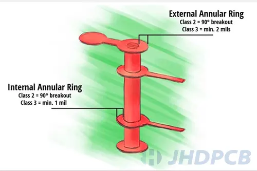
Another major difference between Class 3 and 2 is the breakthrough of drilling.
For the 2 Class ring, in the case of maintaining the minimum horizontal distance, a break of a fracture of less than 90 ° of holes and pads is not a problem.
The 3Class’s printing circuit board should be very reliable. This means that drilling and pads do not allow any breakthroughs, otherwise it may affect the normal use of the product. The minimum internal Annulr Ring of the 3 categories cannot be less than 1 mil, and the external Annular Ring cannot be less than 2 mil.

Annular ring design rules:
2 Class and 3 Class’s Annula Ring tolerance definition is completely different. 3 Class will require more refinement. The factors that determine the Annular Ring process include copper thickness, diameter of drilling, pads, PCB thickness and vertical ratio. The detailed Annulr raing knowledge can be understood on our corresponding page.

Annular ring design rules

These are only part of the difference between 2 and 3 Class. We still recommend that you communicate more with your PCB manufacturer, usually they will guide you and help you achieve your purpose. JHD’s customer service team will also actively communicate with customers when receiving unusual feedback from engineers to ensure the reliability of PCB.

What is the difference between IPC Class 2 and Class 3 for PCB assembly?

IPC classes for PCB are also important. As mentioned earlier, Class 2 products are of slightly lower quality compared to Class 3 products. IPC Class 2 vs Class 3 has its own advantages. In other words, the greater the number of classes, the better their quality level. So, what is the difference between the assembly process of a category 2 and a category 3 product? Here are three notable differences:

Cleanliness and mounting parts are different.
The notable difference between these two courses is the rigor and quality they will endure. Therefore, the cleanliness and installation of the components between the two are different.
Since Class 3 products are used in large quantities in military and medical applications, they require thorough cleaning. In addition, its components must be carefully installed compared to Class 2.
Level 3 assembly is finer than Level 2.
As mentioned above, Class 3 products are very reliable and have a long service life. They are also ideal for high-reliability electronics. The IPC Class 3 annular ring works well. Therefore, this means that their assembly process is improved compared to Class 2.
These products require a careful and detailed assembly process. They are responsible for keeping planes flying in the air and keeping patients alive. Therefore, unlike Class 2 products, the assembly process must be exhaustive. For category 3 products, there are no defects or errors in the assembly process.
Differences in barrel level.
Finally, another differentiating factor between Class 3 and Class 2 products is the full barrel fill that designers use in through-hole leads. Class 2 products consume less drums (50%) than the 75% used for Class 3 products. Conveying the required amount of paste into small plated vias is a very delicate process.

The following table provides a better visual understanding of the difference between Class 2 and Class 3 products:

FactorsIPC Class 2IPC Class 3
Amount of barrel fillThrough-hole leads 50%Through-hole leads 75%
CleanlinessLess thoroughThorough cleanliness
Surface-mount componentsSlightly positional off the pad. While this is a slight optical defect, it doesn’t affect the mechanical and electrical performance.Imperfections, such as visual flaws, aren’t acceptable here. Such marks may see the PCB failing inspection tests.

Verify PCB cross-section for IPC specification.

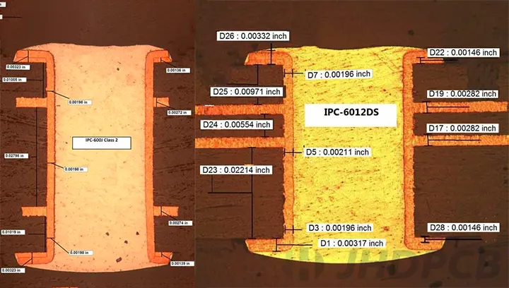
The criteria for inspection are specified by the customer (IPC 6012). Also, the coupon design should follow IPC’s 2220 standard.
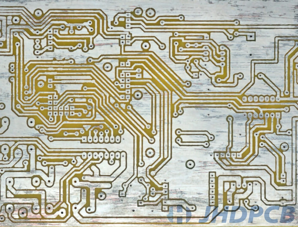
The cross-section or micro-section analysis is a destructive analysis that measures the quality of the manufactured board. It’s basically an interconnection defect analysis process that detects and verifies what went wrong inside the PCB. IPC circuit boards are key. This is an integral part of the PCB manufacturing process.
In other words, it’s a process of inspecting the internal quality of a PCB. The inspection is carried out to determine the quality of the circuit board and also to spot internal failures. The cross -section analysis can check all aspects, such as cracks, welded nodes, and pore filling.
The operation flow of PCB cross-section analysis is as follows:

  • Selection of PCB samples from the production line;
  • Vertical cuts in critical areas of the board to expose cross-sections;
  • Fix the sample to the cross-section analysis holder;
  • Sand the sample and inspect the cross-section for defects using a microscope;
  • Comparison with specifications in IPC Class 2&3 based on real-time observations;
  • Take digital photographs (magnification up to at least 100x) to document identified defects.

PCB cross-sections ipc class2&3

How to choose the right IPC class standard?

Through the above content, I believe you have a preliminary understanding of the IPC standard. So how should we choose the appropriate IPC level standard for our project. JHD will give you suggestions from the following points.
Costs:
As we all know, IPC is divided into Class1, 2, and 3. The higher the level, the stricter the quality inspection conditions. Due to the different types of materials used and the degree of fineness of the process, the relative cost will be higher. You should find the right balance between price and quality.
Application fields:
The scene where the PCB is finally applied also determines which IPC level standard it should use in the manufacturing process. Generally, consumer electronics products can execute Class 2 IPC. In some medical, military and special applications that require more stringent process requirements, Class 3 standards need to be implemented.
Use object:
In the entire PCB supply chain, workers in different links need to implement different IPC standards. For example: the initial designers need to adhere to IPC-2221; and the most used in the manufacturing process is IPC-6011/6012; IPC-A-600 is suitable for acceptance personnel… For the detailed IPC standard type, please refer to the previous content, hoping to be able to to help you choose.

What other important electronics industry standards are there?

In JHDPCB’s production management system, in addition to IPC standards, several other common electronic industry standards are also included in product quality management. details as follows:

  • UL: UL certification was founded by UL Co., Ltd., a global testing and certification organization and a standard development organization. Since its founding in 1894, UL has published nearly 1,800 safety, quality, and sustainability standards, more than 70 percent of which have become U.S. national standards, and UL is the national standards development agency for Canada.

    UL-JHDPCB

  • RoHS: RoHS is a mandatory standard developed by EU legislation, and its full name is the Directive on the Restriction of the Use of Certain Hazardous Substances in Electrical and Electronic Equipment. This standard has been officially implemented on July 1, 2006, mainly used to standardize the material and process standards of electronic and electrical products, making them more conducive to human health and environmental protection.

    ROHS-JHDPCB

  • ISO: International Organization for Standardization (ISO): This set of standards mainly covers manufacturing and quality control in various industries and is an international type of standard. As commonly used in the electronics industry: ISO 9000, ISO 9001, ISO 14001. They correspond to quality management, quality assurance and environmental management system certification respectively.

    ISO 9001 JHDPCB

IPC standards are essential to the entire PCB industry. They help ensure product quality, reduce costs, simplify communication, and improve competitiveness and credibility. JHDPCB strictly enforces these standards in order to improve efficiency and product quality, and help our customers realize product value.
Choose JHD, we will provide you with reliable PCB manufacturing services. We have many years of PCB manufacturing experience to escort your project. If you have any questions about the IPC standard of PCB, please feel free to contact us.

Get a PCB Quote Now

Open high-quality PCB manufacturing services in JHDPCB

Leave a Comment