Flexible PCB
directory
What Is A Flexible PCB?
As the name suggests, flex circuits is a bendable PCB, which is used in some products that require a PCB that can be bent. Similar to the structure of rigid PCB, the flexible board uses a layer of PI (Polyimide) with high temperature resistance and good dielectric layer as the base material, and then uses the adhesive layer of Epoxy to bond the copper foil layer on the top layer. If it is a double sided flexible PCB, the upper and bottom layers of copper foil need to be bonded.
For more PCB substrate properties, please refer to “Introduction To The Material Properties Of PCB CCL”

How to Make Flexible PCB?
According to different types of flex circuits, there will be different manufacturing processes. Due to space limitations, we introduce the most common single sided flexible pcb and double sided flexible pcb manufacturing processes below.
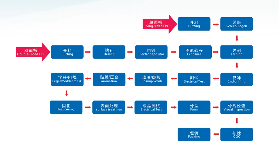
Pcb fabrication process of single sided flexible pcb :
- Flexible pcb manufacturer slitting cut the roll-shaped polyimide copper flexible base material into the flexible pcb board size required by customers with a cutting machine.
- The circuit is developed and transferred to the copper foil by exposure etching.
- Etching Part of the developed circuit is retained, and other residual parts are etched away.
- The target punch turns out the required holes on the flexible printed circuit boards.
- Use E-testers to test the circuits.
- Cleaning and grinding the tested flexible circuits.
- The copper layer is pasted with a polyimide protective film and lamination is performed.
- Legend and solder mask.
- Curing Bake is performed to cure the solder mask and legends.
- Surface treatment to prevent pad oxidation. The surface treatment methods commonly used for flexible pcb board include OSP, LF-HASL and immersion gold.
- Finished product test: The second test to prevent any bad high quality flexible pcb from flowing out of JHDPCB’s production line.
- Shape: Use a knife mold to cut off the size of the imposition shape required by the customer.
- Appearance inspection: Our FQC department has detected some appearance problems with the naked eye and fix them.
- Packaging: After FQC inspection, the flexible circuits with good appearance will be packaged.
- The OQC department will conduct random inspections to ensure that the number of boxes, marks, labels, etc. are consistent with customer requirements.
The manufacturing process of double-sided FPCB is similar to that of single-sided FPCB:
- Flexible pcb manufacturer slitting cut the roll-shaped polyimide copper flexible base material into the flexible pcb board size required by customers with a cutting machine.
- For the convenience of making via holes on the double sided flexible pcb, it is necessary to perform the first drilling in advance.
- Electroplating is to coat the copper foil with thicker copper. The conventional double sided flexible copper is only 15um or 35um thick. If the customer needs 70um or 105um, then electroplating is required. At the same time, the vias can be plated with copper.
- Graphic transfer: According to the design of GERBERS, transfer the circuit design to the copper foil layer through Exposure.
- Etching Part of the developed circuit is retained, and other residual parts are etched away.
- The target punch turns out the required holes on the flexible printed circuit boards. To understand what types of holes are generally found on PCB boards, please refer to the JHD hole article.
- Use E-testers to test the circuits.
- Cleaning and grinding the tested flexible circuits.
- The up and down copper layers are pasted with a polyimide protective film and lamination is performed.
- Legend and solder mask.
- Curing Bake is performed to cure the solder mask and legends.
- Surface treatment to prevent pad oxidation. The surface treatment methods commonly used for flexible pcb board include OSP, LF-HASL and immersion gold.
- Finished product test: The second test to prevent any bad high quality flexible pcb from flowing out of JHDPCB’s production line.
- Shape: Use a knife mold to cut off the size of the imposition shape required by the customer.
- Appearance inspection: Our FQC department has detected some appearance problems with the naked eye and fix them.
- Packaging: After FQC inspection, the flexible circuits with good appearance will be packaged.
- The OQC department will conduct random inspections to ensure that the number of boxes, marks, labels, etc. are consistent with customer requirements.
What Materials Make up a Flex Circuit Board?
The materials that make up the high quality flexible pcb mainly include PI (polyimide)layer, copper foil layer, and cover film.
PI Layer: The polyimide layer as a flexible pcb stiffener,it can strengthen the mechanical strength of the flexible circuits, and the common thickness of PI layer is between 20-35um.
Copper Foil Layer: The copper foil layer can realize circuit conduction, and the common thickness of copper foil layer is between 1OZ-3OZ. Copper foil materials are divided into two types: electrolytic copper and rolled copper. Rolled copper is softer than electrolytic copper and can be bent multiple times without breaking. If the flexible board needs to be bent multiple times and accept higher flexible pcb cost, JHDPCB-flexible pcb manufacturer recommends using rolled copper for flexible pcb fabrication.
Cover Film: The cover film is equivalent to a solder mask, which can protect the circuit from being oxidized and can function as a solder mask. The common thickness is between 18-50um.
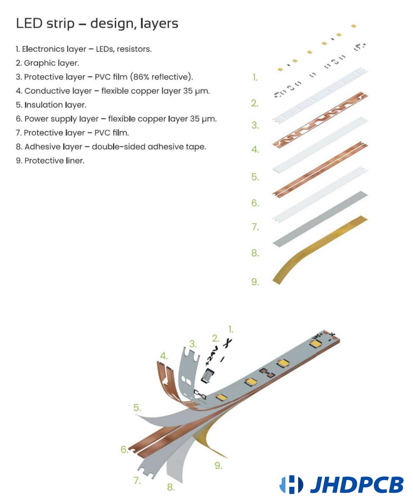
In order to understand the structure of the soft board more intuitively, let’s take led flexible pcb as an example to introduce the specific structure of the flexible pcb board in layers:
- Electronics layer- leds, resistors;
- Graphic layer;
- Protective layer- PVC film(86% reflective);
- Conductive layer-flexible copper layer;
- Insulation layer;
- Power supply layer-flexible copper layer;
- Protective layer-PVC film;
- Adhesive Layer- double sided adhesive tape;
- Protective liner;
Read more about the relationship between FPC and LED strips and application performance knowledge.
What are Features of Flexible Circuit PCB?
Generally speaking, the product features of flex circuits are that it can be bent, flexible pcb material is soft and light, and the flex circuits thickness is thin and light. The flexible pcb material used in the flexible board can be bent many times without breaking the insulation layer or copper foil layer due to its flexible nature. Flexible circuits are made of polyimide or similar polymers. This material dissipates heat better than most rigid circuit board materials. For this reason, flexible circuits can be replaced where heat affects the performance of rigid circuit boards.
High temperature resistance usually has good chemical resistance and excellent resistance to radiation and ultraviolet light. Combined with the ability to control impedance in high-density circuit board designs, flexible circuit design provides many benefits for manufacturers.
Flexible circuit boards can be designed to withstand extreme temperatures-between -200° C and 400° C-which explains why they are so suitable for borehole measurement in the oil and gas industry.
In most industrial environments, smaller and more practical devices are required. Because of these conditions, flexible circuits represent the first choice for engineering design in most industrial sensor technologies.
But the flexible pcb also has its own limitations. Because of the flexible pcb material and the compact layout of the flex circuits design, the Flexible Circuit PCB cannot withstand high on-current and voltage. Therefore, flexible pcbs are not suitable for high-power products, but only for electronic products with low current and low power. In these fields, the use of flexible printed circuit boards is very large.
Where to Buy Flexible PCB Board?
With the decline of flexible pcb manufacturers in Japan and South Korea and the wide application of 5G, a number of excellent china flexible pcbs manufacturers have emerged, such as HON-FLEX, CEEPCB, KINWONG, JHDPCB and other companies. The first three focus on the production of micro-flex boards, such as those for iPhones and Android phones. JHDPCB is more focused on the production of standard single-sided flexible pcb and double-sided flexible pcb, such as flexible pcb led strip.
So purchasing flexible pcb board in China is a right choice, you can choose different china flexible pcb manufacturers according to your product application etc.
What are Our Flexible PCB Manufacturing Capabilities?
Specifications
| Category | Capability | Details |
|---|---|---|
| Board Size | Min(pcs) | 1*0.5mm |
| Max (Pnl Size) | 250*1200mm | |
| Base Material Thickness | 0.06——0.3mm | |
| Board Thickness | 0.1-0.5mm | |
| Base Copper Thickness | 1/3OZ——2OZ | |
| PTH Hole Wall Copper Thickness | 8-20μm | |
| Blind Hole Filling Capacity Aspect Ratio (Hole Size: Hole Depth) | 01:10:00 | |
| Blind Hole Filling Capacity (Hole Size) | 50-150μm | |
| Single Line Impedance Tolerance | ±10% | |
| Differential Impedance Tolerance | ±10% | |
| Min Track/Spacing (Double Layers Board) | Surface Copper Thickness:8-14μm | 40/40 um |
| Surface Copper Thickness:15-20μm | 45/45 um | |
| Surface Copper Thickness:21-30μm | 55/55 um | |
| Surface Copper Thickness:31-40μm | 75/75 um | |
| Surface Copper Thickness:≥40μm | 80/80 um | |
| Line Width Tolerance | Line Width≤0.050mm | ±.02mm |
| 0.05mm<Line Width≤0.15mm | ±20% | |
| Line Width>0.150mm | ±10% | |
| Silkscreen | Silkscreen Character Min Width/Spacing | 4mil |
| Impedance | Green Solder Mask Thickness Range | 10~30 μm |
| Related Capacity | Dimension Tolerance from Line Edge to Plate Edge | ±0.25 mm |
Drilling & Hole
| Category | Capability | Details |
|---|---|---|
| Width Tolerance of White Line | Smooth Place | ±0.10 mm |
| Bump Place | ±0.20 mm | |
| Min Drilling Hole Size | Machine Dril | 0.100 mm |
| Min Punching Hole Size | N/A | 0.50 mm |
| Complete Hole Size Tolerances | PTH | ±0.050 mm |
| NPTH | ±0.025 mm |
Surface Treatment
| Category | Capability | Details |
|---|---|---|
| Nickel Gold Plating | Nickel Thickness | 40~ 314U” |
| Nickel Th | ±78U” | |
| Gold Thickness | 1.18U” ~ 40U” | |
| Min Spacing (Golden Finger or Pad) | 35um | |
| Nickel Gold Immersion | Nickel Thickness | 40 ~ 236 U” |
| Nickel Th | ±40U” | |
| Gold Thickness | 1U” ~ 3 U” | |
| Min Spacing (Golden Finger or Pad) | 40um | |
| OSP | OSP Thicknes | 6U”~20U” |
What are the common types of flexible PCBs?
Single sided flexible PCB – The simplest flex circuits on the market. They build up a single copper layer on the top of polyimide layer. The production process of single-sided flexible pcb is relatively simple, so the price is also cheap. flexible PCB led strip fall into this category.
Double sided flexible pcb – Similar to the flexible pcb manufacturing process of single-sided, the difference is that the double-sided flexible pcb needs to be drilled first, and then electroplated to make via holes to connect the upper and lower layers of circuits. When the single-sided fpc is not enough for laying lines, double-sided flexible pcb should be considered. Double-sided flexible pcb are more expensive than single-sided flexible pcb.
Multi-Layer flexible pcb – with four or more layers of conductor copper. Multilayer flexible pcb have higher precision and space, and they are usually used in high-precision products. Since the manufacturing process of the Multi-Layer flexible pcb is relatively complicated, the cost is also relatively high.
Rigid-Flex flexible pcb – On the basis of rigid circuit boards, combined with flex circuits. Has the advantages of both rigid pcb and flexible pcb . Often used in consumer electronic products, such as tablet computers, mobile phones, etc.

The Differences Between FPC With Rigid PCBs.
· Manufacturing process
Most of the manufacturing steps of FPCs and rigid PCBs are similar. But FPCs need some tools to hold them in a fixed position because of its flexibility.
· Material
The dielectric layers in FPCs are typically homologous sheets of flexible polyimide material. While The dielectric materials in rigid PCBs are usually the composite of epoxy and glass fiber woven cloth. For detailed substrate materials, please refer to “What Is CCL? And Classification Methods”
· Price
From the perspective of the price alone, FPCs are more expensive than rigid PCBs. But FPCs have plenty of benefits to improve the cost performance, like space-saving, weight-reducing, and high reliability, etc.
· Solder Mask
There is a layer of solder mask on both sides of a rigid PCB. The solder mask has gaps, and the SMT pads or PTH holes are exposed to allow components to assemble. FPC usually use a cover coat instead of a solder mask. The cover coat is a thin polyimide material that can be drilled or laser-cut to access the components.
What are the disadvantages of Flexible PCB?
Although flexible printed circuit boards have various advantages such as light weight and bendability, they also have their own limitations. The flexible pcb board cannot withstand high current or high voltage. On the other hand, if there is a problem with the flexible pcb board, it is not easy to repair.

Although flexible PCB still cannot completely replace rigid PCB, it has many unique advantages in some specific fields. Of course, the requirements for equipment and teams in the manufacturing process should not be underestimated. JHDPCB is an experienced PCB manufacturer with more than 10 years in the production of flexible PCBs. Our continuous introduction of first-class equipment, supported by an experienced team of experts, has grown into an industry-leading flexible PCB manufacturer, providing customers with reliable quality flexible PCBs. (Click to see JHD’s advantages in flexible PCB) If you need more details or other assistance, please contact us.


